Service Manual
46 Pages
Preview
Page 1
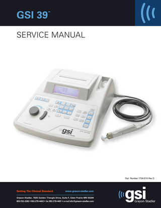
GSI 39
™
SERVICE MANUAL
Part Number 1739-0110 Rev D
Setting The Clinical Standard
www.grason-stadler.com
Grason-Stadler, 7625 Golden Triangle Drive, Suite F, Eden Prairie MN 55344 800-700-2282 • 952-278-4402 • fax 952-278-4401 • e-mail [email protected]
GSI 39
Unpacking and Inspection
The GSI 39 Auto Tymp (hereafter referred to as ‘instrument’ in this guide unless otherwise noted for clarity) is a versatile combination instrument that provides testing capability for tympanometry alone, tympanometry combined with screening acoustic reflex measurements, and screening audiometry. Five different versions are available.
• •
Version 1 provides two modes of operation, tympanometry alone and tympanometry plus screening ipsilateral acoustic reflex testing.
•
Version 3 provides testing capability for all three test modes, i.e., tympanometry alone, tympanometry combined with ipsilateral and contralateral screening acoustic reflex measurements, and screening audiometry, both manual and automated.
•
Version 4 allows tympanometry alone, tympanometry combined with ipsilateral acoustic reflex screening testing, and manual and automated screening audiometry.
•
Version 5 is for tympanometry only.
Version 2 permits tympanometry alone and tympanometry combined with ipsilateral and contralateral screening acoustic reflex measurements.
It is possible to field upgrade versions 1, 2, 4 and 5 with the full functionality provided with version 3 after the time of original purchase. Each version can be fitted with the Combo Probe that allows for both 226 Hz and 1000 Hz probe tone. 1000 Hz probe tone is recommended for testing on infants 0 - 6 months of age. An optional soft-sided carrying case is available for portability. Also, a patient handswitch, patch cords, and earphone sound enclosures may be purchased as optional accessories.
Unpacking and Inspection Although your GSI 39 was carefully tested, inspected and packed for shipping, it is good practice after receiving the instrument to immediately examine the outside of the container for any signs of damage. Notify your GSI representative if any damage is noted. Carefully remove your GSI 39 from its shipping container. If the instrument appears to have suffered mechanical damage, notify the carrier immediately so that a proper claim can be made. Be certain to save all packing materials so that the claims adjuster can inspect it as well. As soon as the carrier has completed the inspection, notify your GSI representative. If the instrument must be returned to the factory, repack it carefully in the original shipping container (if possible) and return it to the factory for necessary adjustment. Check that all the accessories are received in good condition. If any accessories are missing, notify your GSI representative immediately. See the Specifications section later in the preface for the catalog numbers of accessories and also for a listing of all optional accessories.
1739-0110 Rev. D
i
Supplied Accessories GSI 39 (226 Hz only)
Standard Probe (226 Hz version)
1739-3200
Contra Insert Phone (Versions 2 and 3 only)
8000-0079
TDH-39 Headset (Versions 3 and 4 only)
8000-0175
DD45 Headset (Versions 3 and 4 only)
8000-0181
HDA 200 Headset (Versions 3 and 4 only)
1761-0590
Test Cavity (226 Hz)
1700-1030
Power Supply (Power cord per country kit ordered)
113-405800
Eartips, (Probe) 6 sizes, 2 each (all versions)
1700-9622
Eartips, (Contra Insert Phone) color coded, 8 sizes, 4 each (Versions 2 & 3 only)
1700-9660
Paper 3 rolls, thermal 4" wide (all versions). Shipped with instrument. Note: To reorder a single roll of paper, use the following part number:
GSI 39 (226 Hz and 1 kHz)
1738-9601
User Manual (all versions)
1739-0100
Wall chart (226 Hz)
1739-0160
Combo Probe (226 Hz / 1 kHz version)
1739-3250
Contra Insert Phone (Versions 2 and 3 only)
8000-0079
TDH-39 Headset (Versions 3 and 4 only)
8000-0175
DD45 Headset (Versions 3 and 4 only)
8000-0181
HDA 200 Headset (Versions 3 and 4 only)
1761-0590
Test Cavity (226 Hz)
1700-1030
Power Supply (Power cord per country kit ordered)
113-405800
Eartips, (Probe) 6 sizes, 2 each (all versions)
1700-9622
Eartips, (Contra Insert Phone) color coded, 8 sizes, 4 each (Versions 2 & 3 only)
1700-9660
Paper 3 rolls, thermal 4" (10.16 cm) wide (all versions). Shipped with instrument. Note: To reorder a single roll of paper, use the following part number: User Manual (all versions)
1739-0100
GSI 39 Quick Guide
1739-0180
Probe Cleaning Kit
2000-9610
Probe Mount - Shoulder
1700-9646
Probe Mount - Wrist
Optional Accessories
1738-9601
Dust Cover Carrying Case Patch Cord (1 each) Subject Response Handswitch Audiocups Earphone Sound Enclosures Service Manual Insert Phone Assembly 3A (50 ohm impedance) Insert Phone Assembly 5A (50 ohm impedance) Probe Mount - Clothes
1700-9642
1738-9620 1738-9680 4204-0505 7874-0156 8000-0155 1739-0110 1700-9606 1700-0882 1700-9608
! WARNING Use only GSI supplied components and accessories. ii 1739-0110 Rev. D
GSI 39
Warnings
!
WARNING
The GSI 39 should not be used if there is physical damage to any portion of the base and/or accessories. If the instrument has been dropped or damaged in transit, effects of damage should be assessed before being used for testing purposes. A GSI provided Probe Tip must be used. Using the probe without the Probe Tip could result in injury to the subject. 1. Only use GSI approved parts and accessories. 2. Parts which may be broken or missing or are visibly worn, distorted or contaminated should be replaced immediately with clean, genuine, replacement parts manufactured by or available from GSI. 3. It is recommended that all repairs be performed by a qualified GSI service representative only. Any malfunctions resulting from improper maintenance or repair by anyone other than an authorized GSI representative voids all warranties.
1739-0110 Rev. D
iii
Specifications
Regulatory/Safety Standards:
UL 60601-1 (2003) Medical Electrical Equipment, Part 1, General Requirements for Safety, 2nd Edition IEC/EN 60601-1 Medical Electrical Equipment, Part 1, General Requirements for Safety CSA/C22.2 No.601-1-M90 (2003) Medical Electrical Equipment, Part 1, General Requirements ANSI S3.39-1987 Aural Acoustic Impedance Admittance (Type 3) IEC 60645-5 (2004) Aural Acoustic Impedance/ Admittance (Type 2) ANSI S3.6-2004 Specifications for Audiometers (Type 4) IEC 60645-1 (2002) Pure Tone Audiometers (Type 4) IEC/EN 60601-1-1-2 (2001) Medical Electrical Equipment, Part 1, Electromagnetic Compatibility GL2005-00014 (ASHA 2005) Guidelines for Manual Pure-Tone Threshold Audiometry ISO 8253-1 (1989) Acoustics - Audiometric test methods
Compliance The compliance mark CE0344 identifies compliance with the Medical Device Directive 93/42/EEC.
!
Attention, consult accompanying documents.
GSI is an ISO 13485-certified corporation. Protective Classification: This instrument is intended for continuous operation and has a protective classification of Class 1.
Class 1 Type B
Tympanometry modes Probe Tone: Sound Pressure Level: Harmonic Distortion: Admittance (Compliance) Range:
226 Hz, ±2%; 1000 Hz ±2% 226 Hz: 85.5 dB SPL, ±2.0 dB, measured in an IEC 60318-5 2.0 cc coupler 1000 Hz: 75 dB SPL, ±2.0 dB, measured in an IEC 60318-5 2.0 cc coupler <3% 226 Hz: 0.0 to 1.5 cm3 or 0.0 to 5.0 cm3 1000 Hz: 0.0 to 5.0 mmho and 0.0 to 10 mmho Notes:
1739-0110 Rev. D
1.
The range is automatically selected based upon the amplitude of the tymp peak.
2.
The maximum uncompensated (ECV + tympanogram peak) admittance (compliance) range is 0 to 5.0 cm3 for 226 Hz.
3.
ECV/cavity limits for initiating pressurization is 0.2 to 5.0 cm3. Compliance Accuracy: ±0.1 cm3 or ±5%, whichever is greater for 226 Hz.
vi
GSI 39 Pneumatic System Pressure Range:
+200 to -400 daPa NOTES: 1. 1 daPa approximately = 1.02 mmH20 2. For 226 Hz probe tone, pressure sweeps to at least -100 daPa. To save test time, pressure sweep stops when tympanogram returns to baseline after -100 daPa. 3. For 1000 Hz probe tone, pressure sweep does not stop until -400daPa. 4. Full pressure sweep for 5 cm3 from sea level to 7000 ft. altitude with no leak.
Pressure Accuracy:
±10 daPa or ±15%, whichever is greater, measured in 0.5 to 2.0 cc cavities.
Rate of Sweep:
226 Hz: 600 daPa/sec except near tympanogram peak where sweep rate slows to 200 daPa/sec to provide better definition of peak compliance. 1000 Hz: constant 200 daPa/sec, ±10 daPa/sec
Direction of Sweep:
Positive to negative
Tymp Test Time:
226 Hz: Approximately 1 second 1000 Hz: Approximately 3 seconds NOTE: High compliance tympanograms will take somewhat longer.
Gradient:
226 Hz only: Measurement of the tympanogram pressure width taken at 50% of peak compliance.
Acoustic Reflex Stimuli Frequencies:
226 Hz Probe Tone: 500, 1000, 2000, and 4000 Hz for both ipsilateral and contralateral stimulation 1000 Hz Probe Tone: 500, 2000 and 4000 Hz for both ipsilateral and contralateral stimulation
Accuracy:
±3%
Total Harmonic Distortion: <5% for outputs less than 110 dBHL and <10% at 110 dBHL Rise/Fall Time:
5 to 10 msec
Transducers IPSI:
GSI probe design
CONTRA:
Single Audiovox Model SM-N insert phone (Version 2 and 3 only)
Output Levels: IPSI:
For 226 Hz Probe Tone: 500 and 4000 Hz: 80, 90,100 dB HL (Combo Probe 4000 Hz 80 and 90 dB HL only) 1000 and 2000 Hz: 85, 95, 105 dB HL For 1000 Hz Probe Tone: 500 and 4000 Hz: 80 and 90 dB HL 2000 Hz: 85 and 95 dB HL
CONTRA:
For 226 Hz Probe Tone: 500, 1000, 2000,4000 Hz: 90, 100, 110 db HL For 1000 Hz Probe Tone: 500, 2000 and 4000 Hz: 90 and 100 dB HL NOTES: 1. 226 Hz Probe Tone: Ipsi stimuli are time multiplexed with probe tone (93 ms ON, 66 ms OFF). 1000 Hz Probe Tone: Ipsi stimuli are time multiplexed with probe tone (62 ms ON, 62 ms OFF). 2. Contra stimuli are steady tones. 3. Stimuli are presented at lowest level first. If there is no response, the intensity is increased by 10 dB until a response is detected or the maximum dB HL is reached. 4. Contra is available with Versions 2 and 3 only.
v
1739-0110 Rev. D
Pressure:
226 Hz Probe Tone: Reflex measures are set automatically to pressure at peak compliance with an offset of -20 daPa if peak pressure is negative and +20 daPa if peak pressure is positive. 1000 Hz Probe Tone: Reflex measures are taken at 0 daPa regardless of peak pressure.
Reflex Determination:
3
226 Hz: Compliance change of 0.05 cm or greater. 1000 Hz: Compliance change of 0.1 mmho.
Reflex Test Time:
1 to 12 seconds depending upon the number of ipsi and/or contra test frequencies selected (4 maximum) and intensity required.
Probe LED Indicators 226 Hz Probe: Steady yellow: Blinking green: Steady green: Steady orange: No Light: Combo Probe: Blinking green: Steady green: Steady orange: Blinking orange: No light:
Occlusion Ready to start Test in progress Leak in pressure Test complete. Remove Probe Ready to start Test in progress Occlusion Leak in pressure Test is finished, but further tymps can be run. For 1 kHz tymps with Auto Start off, indicates that more tymps may be performed.
Audiometry mode (Versions 3 and 4 only) Frequencies:
125, 250, 500, 750, 1000, 1500, 2000, 3000, 4000, 6000, 8000 Hz
Accuracy:
±2%
Total Harmonic Distortion: < 2.5% (125 to 3000 Hz measured acoustically at maximum dB HL; 4000 through 8000 Hz measured electrically)
Transducers Audiometric Headset:
Paired TDH-39 (60 ohm) or DD45 (10 ohm) earphones with Type 51 cushions, Versions 3 & 4 only. Headband force per ANSI S3.6 and IEC 60645-1 (4.5 ±0.5) HDA 200 High Frequency Headphones (40 ohm), Versions 3 & 4 only, Headband force = 10N±1N.
Insert Earphones:
ER-3A or ER-5A Insert earphones (50 ohm impedance)
Intensity Levels TDH-39 Headphones
DD45 Headphones
Insert Phones
HDA 200 Headphones
125 Hz -10 to 50 dB HL 500 to 6000 Hz -10 to 90 dB HL 250 and 8000 Hz -10 to 70 dB HL
125 Hz -10 to 50 dB HL 500 to 6000 Hz -10 to 90 dB HL 250 and 8000 Hz -10 to 70 dB HL
125 Hz -10 to 40 dB HL 500 to 4000 Hz -10 to 80 dB HL 6000 Hz -10 to 70 dB HL 250 and 8000 Hz -10 to 60 dB HL
125 Hz -10 to 50 dB HL 500 to 6000 Hz -10 to 90 dB HL 250 and 8000 Hz -10 to 70 dB HL
NOTE: An additional +10 dB is available per frequency via the +10 dB button. Accuracy:
125 to 4000 Hz ±3 dB 6000 and 8000 Hz ±5 dB
Step Size:
5 dB
Signal-to-Noise Ratio:
> 70 dB in 1/3 octave measured at 60 dB HL and higher
Rise/Fall Time:
20 to 50 msec
1739-0110 Rev. D
vi
GSI 39 Tone Format Tone is normally off until the Present bar is depressed. Continuous
Tone is steady when present bar is depressed
Pulsed
Tone is pulsed at 2.5/sec (i.e., 200 msec ON, 200 msec OFF)
FM (frequency modulated)
Tone is frequency modulated at a rate of 5 Hz, ±5%
Printer Paper Roll Length:
Approximately 80 feet (960")
Tests/Roll: Versions 1 and 2:
Approximately 420 Tymps/Reflex or 210 people
Versions 3 and 4:
Approximately 230 tests or 115 people
Assumption:
2 Tymps/Reflex + 1 Audiogram per person
Speed:
Approximately 1 minute to print full battery of tests 2 audiograms plus 2 tymp/ reflex (4 frequencies)
External Printer:
Optional Deskjet color printer recognizing PCL3 or PCL3 GUI; 8-1/2" x 11" or A4 format
Power Line Voltage:
100 - 240 VAC (±10%) Note: Universal auto-ranging power supply
Frequency Range:
50 - 60 Hz (±5%)
Power Consumption:
16 watts maximum while printing
Display:
240 x 64 graphical, monochrome LCD
Environmental Temperature: Operating:
59o to 104o F (15o to 40o C)
Warm-up time:
10 minutes for instruments stored at room temperature.
Storage/Shipping:
-93o to 149o F (-69o to 65o C)
Ambient Pressure:
98 kPa to 104 kPa
Humidity:
15% to 95%
Mechanical - Instrument Instrument Dimensions:
12.5" W x 14.5" D x 4.7" H 31.8 cm W x 36.8 cm D x 11.9 cm H
Weight:
5 lbs (2.3 kg) - instrument and probe
Shipping Carton Dimensions:
19.5" W x 22.5" D x 8.25" H 49.5 cm W x 57.2 cm D x 20.9 cm H
Weight:
vii
13.1 lbs (6 kg)
1739-0110 Rev. D
GSI 39 Catalog Listings: GSI 39 Auto Tymp
226 Hz only
Combo 226 + 1k Hz
USA International China USA International China
Tymp + Ipsi V.1
Tymp + Ipsi + Contra V.2
1739-9710 1739-9710INT N/A 1739-9711 1739-9711INT N/A
1739-9720 1739-9720INT N/A 1739-9721 1739-9721INT N/A
Tymp + Ipsi + Contra + Audio V.3 1739-9730 1739-9730INT 1739-9730INTC 1739-9731 1739-9731INT 1739-9731INTC
Tymp + Ipsi + Audio V.4 1739-9740 1739-9740INT 1739-9740 INTC 1739-9741 1739-9741INT 1739-9741INTC
Tymp only V.5 1739-9750 1739-9750INT N/A 1739-9751 1739-9751INT N/A
Country Kits (one must accompany each instrument) Each Country Kit contains a Power Cord, User Manual, Wall Chart and a Quick Reference Guide 1739-9400 1739-9401 1739-9402 1739-9403 1739-9404 1739-9405 1739-9406 1739-9407 1739-9408 1739-9409 1739-9410 1739-9411 1739-9412 1739-9413 1739-9414 1739-9415 1739-9416 1739-9417 1739-9418 1739-9419 1739-9420 1739-9421 1739-9422 1739-9423
North America cord, English CtryKit, North America Cord., Spanish CtryKit, North America Cord, Portuguese CtryKit, North America Cord., French CtryKit, Europe Cord, French CtryKit, Europe Cord, German CtryKit, Europe Cord, Spanish CtryKit, Europe Cord, Portuguese CtryKit, Europe Cord, Russian CtryKit, Europe Cord, English CtryKit, UK-Ireland Cord, English CtryKit, Italy Cord, Italian CtryKit, Italy Cord, Spanish CtryKit, Swiss Cord, German CtryKit, Swiss Cord, French CtryKit, Swiss Cord, English CtryKit, Denmark Cord, English CtryKit, Israel Cord, English CtryKit, South Africa-India Cord, English CtryKit, Australia Cord, English CtryKit, Australia Cord, Chinese CtryKit, North America Europe Cord, Korean CtryKit, North America Cord, Japanese CtryKit, Brazilian Cord, Portuguese
Upgrade Kits 1739-9600 *Upgrade from 226 Hz to 226 Hz + 1000 Hz probe (use same number for all versions) 1739-9612 *Upgrade GSI 39: 226 Hz Version 1 to 226 Hz Version 2 1739-9613 *Upgrade GSI 39: 226 Hz Version 1 to 226 Hz Version 3 1739-9614 *Upgrade GSI 39: 226 Hz Version 1 to 226 Hz Version 4 1739-9623 *Upgrade GSI 39: 226 Hz Version 2 to 226 Hz Version 3 1739-9643 *Upgrade GSI 39: 226 Hz Version 4 to 226 Hz Version 3 1739-9651 *Upgrade GSI 39: 226 Hz Version 5 to 226 Hz Version 1 1739-9651M *Upgrade GSI 39: 226 Hz Version 5 or Version 1 to any other 226 Hz Version 1739-9652 *Upgrade GSI 39: 226 Hz Version 5 to 226 Hz Version 2 1739-9653 *Upgrade GSI 39: 226 Hz Version 5 to 226 Hz Version 3 1739-9654 *Upgrade GSI 39: 226 Hz Version 5 to 226 Hz Version 4 (* All upgrade kits require calibration. Consult your local GSI Distributor for pricing.)
viii
1739-0110 Rev. D
Table of Contents Preface
Unpacking and Inspection ...i Supplied Accessories……………………………………………………………………..ii Warnings………………………………………………………………………………...iii Specifications ...iv
Chapter 1
The microprocessor controls all of the following functions…………..……………...……1 Communication to the Tymp system……………………………….……………………...1 Display drive information………………………………………….………………………1 Monitoring of the Switch Matrix keys……………………………..………………………1 Altitude/calibration mode switch………………………………….……………………….1 Dip switches………………………………………………………………………………..1 Hearing Level control (HL)……………………………………….……………………….1 Pure tone stimulus………………………………………………...………………………1 Attenuator and +10 dB Range Extender…………………………...………………………2 Output routing/control……………………………………………...……………………...2 Print function / control……………………………………………...……………………...2 The Tymp System consists of the following functions...3 Communication to the microprocessor……………………………..…...………………...3 Pump Drive control………………………………………………….……………………3 Monitoring of the pressure transducer output…………………….….……………………3 Probe Tone oscillator (226Hz/1000Hz) and Speaker drive……….….…………………...3 Microphone input level monitoring……………………………….….…………………...3
GSI 39 Circuit Theory
Chapter 2 Calibration
1739-0110 Rev. D
Equipment required ...4 1.0 Routine Calibration ...5 1.1 Default Data…………..………………………………………………………………5 1.1.1 Power up…………………………………………………………………………6 2.0 IPSI & CONTRA calibration...7 2.1 Ipsi Calibration (ALL versions)……………………………...………………………...7 2.2 Contra Calibration……………………………………………………………………...7 2.3 Audiometry Transducer Stimulus Calibration (versions 3 and 4)…….…….…….…...8 2.4 Audiometry Transducer Stimulus Calibration for HDA200 (versions 3 and 4)……...9 3.0 Probe Tone / MIC Cal, Compliance Cal, Pressure Cal ...10 3.1 226 Hz Probe Tone Calibration…………………………….………….……………...10 3.2 1000 Hz Probe Tone Calibration (Optional – perform if equipped with a 1000 Hz probe)…….….…….………….10 226 Hz Compliance Calibration…………………….…….……………..10 Sea Level Adjustment Chart…………………...………………………...11 3.3 1000 Hz Compliance Calibration (Optional – perform if equipped with a 1000 Hz probe)…………………………...11 Altitude-User Check………………..…………………………………...12 3.4 Pressure Calibration…………………...……………………………………………...12 Functional Test……..….……………………………………………………………13 3.5 Setup…………………………………………………………………………………..13 3.6 Tymp Reflex, Ipsi 226 Hz (ALL versions)…………………………………………...13 3.7 Tymp Reflex, Ipsi 1000 Hz (Optional – perform if equipped with a 1000 Hz probe)..13 4.0 Verification test ...14 4.1 Tymp Section (ALL versions)………...……………………………………………...14 4.2 Tymp Section 1000 Hz (Optional – perform if equipped with a 1000 Hz probe)…...14
Chapter 3 IP Version Upgrades
Chapter 4 GSI 39 Error Codes
Chapter 5 Data Transfers
1739-0110 Rev. D
Version Upgrades...15 Version Upgrade Instructions...15
Fatal Application Errors 1-800………………………….………………………………..15 Fatal BSP errors 800-999………………………………………………………………...23 Non-Fatal (NF) Application errors 1000-1799…………………………………………..24 9000………………………………………………………...……………………………….25 Repair/Replacement Parts List………………………..…………………………………..26
Data transfer …...28 Tympanometry and Reflex Test Results Record for 226Hz……………………………...29 Tympanometry and Reflex Test Results Record for 1KHz………………………………32 Audiometry Test Results Record…………………………………………………………34 Notes………………………………………………………………………………………...35
Chapter 1
GSI 39 Circuit Theory The Microprocessor The GSI 39 is controlled by U34, an Atmel AT91SAM9261S microprocessor. The micro has a 32 Bit CPU and built in peripheral devices. It is designed using CMOS technology. On-chip memory includes 16Kbytes data cache, 16Kbytes of instruction cache, 32Kbytes ROM, and 16Kbytes of SRAM. The many functions incorporated by the microprocessor helps to reduce the board space requirements and the need for additional support circuitry.
The microprocessor controls all of the following functions: Communication to the Tymp system A synchronous SPI serial communications data bus is used to transmit and receive TYMP data. A synchronous I2C serial bus is used to communicate with the Analog to Digital converter to pass TYMP A/D data to the microprocessor. The TYMP pump motor hardware is controlled by the microprocessor directly through GPIO pins.
Display drive information Display information to and from the liquid crystal display (LCD) is controlled by the microprocessor through a GPIO serial bus. Six pins are used. The LCD back light is also controlled by another GPIO pin.
Monitoring of the Switch Matrix keys The microprocessor routinely checks the status of the front panel keys for a change in state. The key panel switch outputs are monitored directly by the microprocessor GPIO. If a key switch change occurs, the microprocessor executes the commands associated with the key function. The +10 dB (extended range) key and the reflex control keys (Ipsi, Contra, 500, 1K, 2K, 4K) are active toggle controls (i.e., push on/push off). The Present bar, Subject Response switch, Frequency up/down key, Paper Advance key, and Page keys all function as press and hold controls, where the corresponding function is active only as long as the control is pressed. Single action controls include the mode control keys (Prog, Aud, Tymp, Tymp/Reflex), Tone type keys (FM, Steady, Pulsed), Rout-ing keys (L, R), Memory control keys (Page, M-, M-), and the Printer control keys (Print Screen, Print All, Paper Advance).
Altitude/calibration mode switch The Altitude mode is selected by simultaneously pushing the Hz up/down , and Page buttons. Press +10 dB to enter the calibrations and diagnostic modes from here. (See the Calibration Chapter for more detailed information on calibration.)
Dip switches There are no Dip switches on the GSI 39. All modes are controlled and monitored via the key pad and LCD display.
Hearing Level control (HL) The Hearing Level control dial is connected to a 36 position, 2 bit encoder located on the HL board. The encoder output from the HL board is connected to the microprocessor. In the audiometer mode, this rotary knob selects the volume for hearing level based on the relative position change of the knob from the previous hearing level selection.
Pure tone stimulus The microprocessor controls the signal (sine wave) for the associated Left Earphone, Right Earphone, Ipsilateral, or Contralateral outputs. The foundation of the pure tone is a programmable signal (sine wave) generator U26. The signal generator is programmed to produce out sine waves of specific frequencies. Communications between the microprocessor and the sine wave generator is accomplished using the SPI synchronous serial bus.
1739-0110 Rev. D
1
GSI 39 Attenuator and +10 dB Range Extender The attenuator is a Voltage Controlled Amplifier U22 (VCA). This device has amplification gain, but most of the range is used as an attenuator. The total range of the attenuator is approximately 100 dB. The output of the attenuator may be set to any level within this range by adjusting the DC voltage present at the EC pins of the VCA. This input is connected to a Digital to Analog Converter U24 (DAC) that controls the output level of the VCA. Calibration of the output levels is accomplished by storing the Hearing Level to Sound Pressure Level (RETSP values) value per frequency and transducer in a look up table in FLASH. This information is then inserted into the DAC that controls the VCA to the appropriate output level. The resolution or step size is controllable to within a 0.1 dB increment. The +10 dB extended range may be selected any time that the hearing level is within 10 dB of the maximum non-extended hearing level for all frequencies. This selection allows an additional +10 dB of range above the normal maximum hearing level limit.
Output routing control The output of the VCA is routed to either the left amplifier, the right amplifier, or the Ipsi /Probe Tone Speaker amplifier. When contra is selected, the output is routed through the Contra Phone amplifier. Each output amplifier has a special control line that allows the output to be disabled or shut off to conserve power. This power saving feature also eliminates any unwanted noise from a non selected output.
Print function / control The test results are printed using a thermal print head printer on a paper that is 112mm or approximately 4 inches wide. When the print function is selected, the processor starts building a graphical bit mapped image of the printout. The printout is formatted as specified by the selections made in the Program mode and stored in FLASH. Before printing takes place, the A/D (as directed by the microprocessor) measures the ambient temperature of the print head. The serial print data is transferred from FLASH to the print head by the microprocessor. After the print head input buffer gets loaded, the data is shifted into the print head, print buffer. Seven dot drivers are then individually turned on and off to print the appropriate dots in the line. This process repeats line by line until the complete image is printed.
2
1739-0110 Rev. D
The Tymp System consists of the following functions: Communication to the microprocessor Synchronous communications data associated with the TYMP mode is transmitted using the microprocessors built in I2C and SPI serial communications interface. TYMP A/D data is transferred using the I2C. The TYMP A/D data consists of tone intensity and pressure.
Pump Drive control The pump assembly consists of a DC stepper motor, an air reservoir, a piston, and an infrared transmitter/detector pair. After power up and at the end of a test, the pump piston is returned to the home position. The home position is determined by a state transition of the infrared photo detector of the pump assembly. The infrared photo detector is monitored by the microprocessor. The pump motor coils are driven by the motor driver U37 which is clocked by the pump drive timer. The timer, which resides in the microprocessor, controls the step rate of the pump assembly, which varies with the pressure sweep rate.
•For 226 Hz probe tones, the pump sweeps at a rate of 600daPa/sec until the slope of the tympanogram is sensed and then the sweep rate slows to 200daPa/sec.
•For 1000 Hz probe tones, the pump sweeps at a rate of 200daPa/sec. If a critical leak is detected during the pump sweep, the pump stops until the probe is removed from the ear canal. When the probe is removed from the ear canal, the pump returns to the home position.
Monitoring of the pressure transducer output The pressure transducer output is an input to the A/D U30, which is monitored by the microprocessor. In the Ambient Pressure calibration mode, DAC U25 is used to adjust the gain of the pressure transducer circuit so that the input voltage at the A/D is 1.5 Vdc. This gain adjustment places the pressure transducer output at ambient or zero pressure in the optimum operating range for the A/D converter. When the ambient gain has been established, the microprocessor sets the DAC to the stored value at all times. The pressure span calibration (+200/-400 daPa) is controlled by the technician and is stored by the microprocessor as a software offset.
Probe Tone oscillator (226Hz/1000Hz) and Speaker drive The probe tone frequency is controlled by the microprocessor. The SPI bus is used to communicate with signal (sine wave) generator U19 and DAC (digital to analog converter) U14. The signal generator U19 generates the 226Hz or 1000Hz tone. The DAC U14 controls the intensity of the 226Hz and 1000Hz tones. The output levels or DAC settings are determined by the calibration data and the external volume as measured by the probe microphone.
Microphone input level monitoring The probe microphone signal is routed through a 226Hz or 1000Hz band pass filter U6. FET Switch U18 is used to select the output of the 226Hz or the 1000Hz band pass filter. The selected signal is then routed to the tone variable gain amp DAC U20 and op amp U47. The setting for DAC U20 is determined during calibration. The signal then goes to the RMS AC to DC converter U21. Finally, the signal goes to the A/D U30 where it is read by the microprocessor.
1739-0110 Rev. D
3
Chapter 2
Calibration Equipment required • • • • • • • • • •
4
Type 1 Sound Level Meter 1" Microphone Artificial Ear AE100 2.0cc Coupler, 1700-2005 Manometer Test Cavity 1700-1030 Contralateral Insert Phone (This shall be the insert phone that is (optionally) shipped with the instrument) Headphones (This shall be the headphone set that is shipped with the instrument) 113-405800 Power Supply (This shall be the power supply that is shipped with the instrument) AC Line Cord (Per customer order - This shall be the line cord that is shipped with the instrument)
1739-0110 Rev. D
1.0 Routine Calibration Press and hold the frequency decrease button, then, with the button still depressed, press and hold the frequency increase. With the first two buttons depressed, press and hold the page button. Release all three buttons and immediately press the +10 button for 2 seconds. Please note this may be a blind selection sequence and the display will not change. Press the page button to update the display and enter the calibration mode.
1739-0110 Rev. D
5
GSI 39 1.1 Default Data 1.1.1 Default data may be loaded under special circumstances. Do not load default data unless necessary 1.
Power on the instrument. Simultaneously press the two Hz up/down buttons
,
SETTINGS MAIN MENU then press the +10 dB button. Use the Hz up/down buttons to CAL MODES. Press the Page
2.
Use the Hz up/down Press the Page
,
and the Page ,
button to enter the
to position the display cursor
button to enter the CAL MODES menu.
buttons to position the display cursor to LOAD DEFAULT TYMP/REFLEX.
button – a confirming message will appear (“REALLY – SELECT AGAIN TO CON Press the Page
button to load the Tymp/Reflex defaults. Verify that the display shows”SUCCEEDED”. Press the Page again to go back to the previous menu.
button
! WARNING Do not perform “LOAD DEF XDCR AUDIO.” This will erase Audio Headset and Insert calibrations. If this load is accidentally done, you must redo Audio Headset and Insert Calibrations. Do not perform “LOAD DEF ALL AUDIO.” This will erase calibrations that are done on the Main Circuit Board. If this load is accidentally done, contact GSI Support for help on reperforming the Max Atten Cal and the Audio Slope Cal. 3.
6
Stay in the CAL MODES menu and proceed to the next step.
1739-0110 Rev. D
2.0 IPSI & CONTRA calibration 2.1 Ipsi Calibration (ALL versions) 1.
Use the Hz up/down buttons
2.
Press Page
3.
Place the probe in the 2.0cc coupler of the sound level meter.
4.
Select IPSI on the GSI 39.
5.
Use the Hz up/down buttons , to select 500Hz. The GSI 39 display and HL Knob work as follows in cal mode: Tone bar unpressed: Tone OFF, display shows target HL level. Use the HL Knob to set the target HL level. Tone bar depressed: Tone turns ON, display shows target SPL level. Use the HL Knob to adjust the SLM reading to Target SPL level.
6.
Press the Tone bar to turn the tone on and adjust to the Ipsi Target SPL value listed below. Be sure to add in any mic corrections to the sound level meter.
7.
Press the M+ button to store the data for each frequency. Repeat for all frequencies. Frequency
,
to position the cursor on the GSI 39 display at XDUCER STIM CAL.
to enter Xducer Stim Cal.
HL, dB
Ipsi Target SPL ± 1.5dB
500Hz
90
95.5
1000Hz
95
95.0
2000Hz
95
98.0
4000Hz
90
95.5
Note: SPL Deviation = SLM Measurement – Target SPL as shown on the GSI 39 display.
2.2 Contra Calibration 1.
Select CONTRA on the GSI 39.
2.
Place the insert phone in the 2.0cc coupler of the Sound Level Meter.
3.
Press the Tone bar to turn the tone on and use the HL knob to adjust to the Contra Target SPL value listed below. Be sure to add in any mic corrections to the sound level meter.
4.
Press the M+ button to store the data. Repeat for all frequencies. Frequency
HL, dB
Contra Target SPL ± 1.5dB
500Hz
100
105.5
1000Hz
100
100.0
2000Hz
100
103.0
4000Hz
100
105.5
Note: SPL Deviation = SLM Measurement – Target SPL as shown on the GSI 39 display.
1739-0110 Rev. D
7
GSI 39 2.3 Audiometry Transducer Stimulus Calibration (versions 3 and 4) – for HDA200 see Section 2.4 1.
From the CAL MODES screen, use the keys to position the cursor on the GSI 39 display at XDUCER STIM CAL.
2.
Press the page key to enter the XDUCER STIM CAL mode. The display will appear as follows. XDUCER STIM CAL 40.0 dB 125 Hz TRANSDUCER:
R
STANDARD: ANSI -NBS 9A PRESS M- - TO RESET THIS XDUCER CAL PRESS PRESENT TO ACTIVATE TRANSDUCER Indicates the Type of Transducer Selected 40.0 dB Indicates the Current Hearing Level (HL) Selected 125Hz
Indicates the Current Frequency (Hz) Selected
R
Indicates the Current Transducer (Left or Right) Selected
In this mode, the Tone Bar serves a dual function. Pressing the Tone Bar toggles between the current hearing level (HL) and the ANSI Standard Reference Threshold Level (RTL) for the selected transducer and frequency displayed in SPL. The GSI 39 allows flexibility in which coupler type is used for calibration. The following tables show the ANSI and IEC standards supported by the GSI 39. The values for TDH 39 and Inserts come from the ANSI S3.6-2010 standard and the IEC 60318 standards (ISO 389-1, ISO 389-2). The RETSPL values for the DD45 earphones are based on a combined study performed by PTB - Germany and DTU - Denmark. TDH 39 (dB SPL) Frequency in Hz
IEC 60318-3 (ANSI NBS-9A)
125
45.0
250 500
TDH 39 / DD45 (dB SPL) IEC 60318-1
DD45 (dB SPL)
3A / 5A Inserts (dB SPL)
IEC 60318-3 ANSI NBS-9A
ANSI HA-1
ANSI HA-2
IEC 711
45.0
47.5
26.5
26.0
28.0
25.5
27.0
27.0
14.5
14.0
17.5
11.5
13.5
13.0
6.0
5.5
9.5
750
8.0
9.0
6.5
2.0
2.0
6.0
1000
7.0
7.5
6.0
0.0
0.0
5.5
1500
6.5
7.5
8.0
0.0
2.0
9.5
2000
9.0
9.0
8.0
2.5
3.0
11.5
3000
10.0
11.5
8.0
2.5
3.5
13.0
4000
9.5
12.0
9.0
0.0
5.5
15.0
6000
15.5
16.0
20.5
-2.5
2.0
16.0
8000
13.0
15.5
12.0
-3.5
0.0
15.5
The GSI 39 automatically adds the above ANSI RETSPL and HL values. During calibration only the appropriate microphone correction values need to be added or subtracted. 3. Connect the appropriate transducer to the Sound Level Meter. Ensure the display on the GSI 39 correctly reflects the transducer and type that is to be calibrated. To change the coupler type, the existing transducer cal must first be reset. Press M-- to reset the transducer cal. Then press PROG to change the standard and coupler type. 4.
Press the Tone Bar and the display will update from the selected Hearing Level to the ANSI RETSPL value for calibration.
5.
Adjust the HL knob until the SPL measured on the SLM for the selected frequency and transducer equals the value indicated on the GSI 39 display (+/ – microphone corrections).
6.
Press the M+ key to store the data in memory (SAVED will briefly appear).
7.
Repeat for all frequencies, all transducers (TDH 39, 3A or 5A) Left and Right.
8.
When complete press the Page
8
key to return to the CAL MODES screen. 1739-0110 Rev. D
GSI 39 2.4 Audiometry Transducer Stimulus Calibration for HDA200 (versions 3 and 4) – other transducers see Section 2.3 1.
From the CAL MODES screen, use the keys to position the cursor on the GSI 39 display at XDUCER STIM CAL.
2.
Press the page key to enter the XDUCER STIM CAL mode. The display will appear as follows. XDUCER STIM CAL 40.0 dB 125 Hz TRANSDUCER:
R
STANDARD: ANSI -NBS 9A PRESS M- - TO RESET THIS XDUCER CAL PRESS PRESENT TO ACTIVATE TRANSDUCER Indicates the Type of Transducer Selected 40.0 dB Indicates the Current Hearing Level (HL) Selected 125Hz
Indicates the Current Frequency (Hz) Selected
R
Indicates the Current Transducer (Left or Right) Selected
In this mode, the Tone Bar serves a dual function. Pressing the Tone Bar toggles between the current hearing level (HL) and the ANSI Standard Reference Threshold Level (RTL) for the selected transducer and frequency displayed in SPL. The GSI 39 allows flexibility in which coupler type is used for calibration. In order to calibrate the GSI 39 with the HDA200 (HF) transducers, the ANSI – NBS 9A coupler must be selected on the audiometer display. The coupler physically utilized must be the IEC 60318-1 with a Type 1 Adaptor. The following tables show the ANSI and IEC standards supported by the GSI 39. These values come from the ANSI S3.6-2004 standard and the IEC 60318 standards (ISO 389-1, ISO 389-2). HDA 200 R/L (dB SPL)
Cal Level (dB HL)
Cal Level HL + DD45 RETSPL
IEC 60318-1, Type 1 Adaptor
GSI 39 Display
dB SPL on GSI 39 Display
Cal Level HL + HDA200 RETSPL dB SPL on SLM
Frequency in Hz
DD45 R/L (dB SPL) (v1.09) ANSI NBS-9A
125
47.5
30.5
40
87.5
70.5
250
27.0
18.0
60
87.0
78.0
500
13.0
11.0
80
93.0
91.0
750
6.5
6.0
80
86.5
86.0
1000
6.0
5.5
80
86.0
85.5
1500
8.0
5.5
80
88.0
85.5
2000
8.0
4.5
80
88.0
84.5
3000
8.0
2.5
80
88.0
82.5
4000
9.0
9.5
80
89.0
89.5
6000
20.5
17.0
80
100.5
97.0
8000 12.0 17.5 60 72.0 77.5 The GSI 39 automatically adds the above ANSI RETSPL and HL values. During calibration of the HDA200, the correction values are made as described below with the GSI 39 display showing the corrected values in the shaded column. The additional correction values for the HDA200 will need to be added or subtracted with the resulting values in the last column which will be displayed on the SLM. 3. Connect the appropriate transducer to the Sound Level Meter. Ensure the display on the GSI 39 reflects the transducer type that is to be calibrated. To change the coupler type, the existing transducer cal must first be reset. Press M-- to reset the transducer cal. Then press PROG to change the standard and coupler type. For each step, verify that the correct Cal Level is displayed for each frequency. (Note: this can only be viewed when the tone bar is deactivated and may need to be adjusted at 6000Hz) 4.
Press the Tone Bar and the display will update from the selected Hearing Level to the ANSI RETSPL value for calibration.
5.
Adjust the HL knob until the SPL measured on the SLM for the selected frequency and transducer equals the value shown in the last column of the table above (+/ – microphone corrections).
6.
Press the M+ key to store the data in memory (SAVED will briefly appear).
7.
Repeat for all frequencies, when complete press the Page
1739-0110 Rev. D
key to return to the CAL MODES screen. 9