VIASYS Healthcare
Grason-Stadler Tympanometry
GSI TympStar Versions 1 and 2 Service Manual Rev B Jan 2011
Service Manual
224 Pages
Preview
Page 1
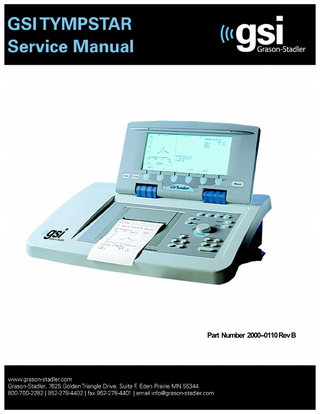
Part Number 2000--0110 Rev B
Title:
GSI TympStar Versions 1 and 2 Middle-Ear Analyzer Service Manual
Date:
January, 2011
Copyright © 2011 Grason-Stadler. All rights reserved. No part of this publication may be reproduced or transmitted in any form or by any means without the prior written permission of Grason-Stadler. The information in this publication is proprietary to Grason-Stadler. Part number:
2000-0110
Printing history:
November, 2001 June, 2002 October, 2002 March, 2008 June, 2010 January, 2011
First printing Second printing Third printing Fourth printing Fifth printing Sixth printing
Rev 1.0 Rev 2.0 Rev 3.0 Rev 4.0 Rev A Rev B
Warranty for the GSI TympStar Versions 1 & 2 Grason-Stadler warrants the GSI TympStar Versions 1 and 2 to be free of original defects in material and workmanship and to perform in accordance with manufacturer’s specifications for a period of one year from the date of purchase. If this instrument or any component thereof is found to be defective or at variance from the manufacturer’s specifications during the warranty period, Grason-Stadler will repair, replace, or recalibrate the instrument or component at no cost to the purchaser. This warranty only applies to instruments purchased new from Grason-Stadler or its authorized distributors or representatives. The purchaser must return the instrument directly to Grason-Stadler or an authorized GSI TympStar distributor or representative and bear the costs of shipping. This warranty does not cover breakage or failure due to tampering, misuse, neglect, accidents, modification, or shipping, and is void if the instrument is not used in accordance with manufacturer’s recommendations or if repaired or is serviced by other than Grason-Stadler or a Grason-Stadler authorized representative.
WARNING The GSI TympStar Versions 1 and 2 are designed to be used with a hospital grade outlets. Injury to personnel or damage to equipment can result when a three-prong adapter is connected between the instrument’s power plug and an A/C outlet or extension cord.
Accessory Hazard Warning This IEC 601-l/CSA C22.2 No. 601.1M90 listed medical instrument should be interconnected with accessories that have proper electrical compatibility and which are listed as conforming to Part 1: General Requirements for Safety of the UL Medical Electrical Equipment Standard UL2601-1. Connection of accessories not meeting these requirements may result in electrical leakage currents in excess of those allowed by the standard and present a potential electrical shock hazard to the person being tested.
User manuals
Installation, setup and operating information can be found in the Reference Instruction Manuals: TympStar Version 1: 2000-0100 TympStar Version 2: 2000-0120
Service personnel
Repair and/or bench testing of the GSI TympStar Version 1 and Version 2 instruments should be performed only by trained personnel. The following instructions are provided primarily for use by persons who are skilled in the repair of electronic equipment.
Electrical safety
CAUTION The GSI TympStar Version 1 and Version 2 instruments are IEC 601-1/CSA approved; consequently, if any parts are replaced during the repair of these units, only exact replacements should be made. Any alterations of the present electrical or mechanical construction or components will void these safety approvals.
CMOS handling
Many of the integrated circuits on the PC Boards are constructed of CMOS and NMOS materials. Please observe the following precautions: CAUTION Failure to observe the following precautions whenever a circuit board or an integrated circuit package is handled can result in damage to the GSI TympStar Version 1 or Version 2 instrument. Please observe these precautions: 1) Place the instrument and parts on a grounded, conductive work surface. 2) Ground yourself (with a strap having about 1 Meg-Ohm resistance) to discharge or prevent static charges. 3) Ground the frame of any test instrument or soldering iron to be used. 4) If any circuit boards are to be stored or transported, enclose them in conductive (antistatic) envelopes.
Contents Introduction ...1-1 General ... 1-1 Version 1 ... 1-2 Version 1 equipment connections and options ... 1-2 Version 2 ... 1-3 Version 2 equipment connections and options ... 1-3 The probe ... 1-4 Instrument controls ... 1-5 Hardkeys and softkeys ... 1-5 Rotary pressure control ... 1-5 Test modes and menu navigation ... 1-5 Changing parameter settings... 1-7 Menu diagrams ... 1-7 GSI default parameter settings ... 1-7
Specifications ...2-1 Introduction ... 2-1 Standards ... 2-1
Version 1 Specifications ... 2-1 Sensitivity ranges ... 2-2 Probe signal ... 2-2 Pneumatic System ... 2-3 Acoustic Reflex Activating (Stimulus) Signal ... 2-3 Stimulus Presentation Control ... 2-5 Temporal Specifications of Stimulus Presentation ... 2-5 Environmental ... 2-6 Warm-Up Time... 2-6 Calibration Stability ... 2-7 Connectors ... 2-7 Electrical ... 2-8 Supplied Accessories ... 2-9 Mechanical ... 2-9 Materials of manufacture ... 2-9
GSI TympStar Version 1 and Version 2 Service Manual
Contents - 1
Table of Contents
Calibration requirements ... 2-9
Version 2 Specifications ... 2-10 Standards ... 2-10 Sensitivity ranges ... 2-11 Temporal Latency in ARLT Mode... 2-12 Multi Frequency ... 2-12 Probe Signal (Sinusoidal) ... 2-12 Pneumatic System ... 2-13 Acoustic Reflex Activating (Stimulus) Signal ... 2-13 Click Stimulus ... 2-16 Stimulus ... 2-16 Presentation Control... 2-16 Temporal Specifications Of Stimulus Presentation ... 2-17 Environmental ... 2-17 Warm-Up Time... 2-17 Calibration Stability... 2-18 Connectors ... 2-18 Electrical ... 2-19 Supplied Accessories ... 2-20 Mechanical ... 2-20 Materials of manufacture ... 2-20 Calibration requirements ... 2-20
Operation summary...3-1 Front panel controls ... 3-1 Hardkeys... 3-2 Tymp ... 3-2 Reflex ... 3-2 Etf ... 3-2 Special ... 3-2 Page ... 3-2 Print ... 3-2 Remote ... 3-2 Data Transfer ... 3-2 Pressure control ... 3-2 Manual ... 3-2 Hold ... 3-2 Stop ... 3-2 Start ... 3-3 Stimulus ... 3-3 Intensity ... 3-3
Contents - 2
Grason-Stadler
Table of Contents
Present ... 3-3 LCD hardkeys... 3-3 Clear ... 3-3 Erase ... 3-3 Return... 3-3 Softkeys ... 3-3
Menus and LCD screens ... 3-4 Menus ... 3-4 Program modes... 3-5 Version 1 probe tone frequencies ... 3-5 Version 2 probe tone frequencies ... 3-5 Version 1 LCD graphic traces ... 3-5 Version 2 LCD graphic traces ... 3-5 Probe lights ... 3-6 LCD screen ... 3-6 Erasing and clearing test data ... 3-7 Version 2 External reflex test stimuli ... 3-7 Paging test data ... 3-7 Version 2 cursor... 3-8 Printing tests ... 3-8 Preparing an external printer ... 3-8 Setting the printer parameters ... 3-9 Left column printout data ... 3-10 Color or black and white ... 3-10
Changing Instrument Versions ... 3-11 Changing from a Version 2 to a Version 1 ... 3-11 Switching to V1 temporarily... 3-12 Switching back to V2 ... 3-12 Switching to V1 permanently ... 3-12 Changing from a Version 1 to a Version 2 ... 3-13 Obtaining a License Code ... 3-14 Replacing the V1 Probe with a V2 Probe ... 3-15 Switching to Version 2 software ... 3-16
Version 1 test procedures ... 3-17 Tymp diagnostic... 3-17 Manual Tymp ... 3-17 Tymp screening ... 3-18 Reflex threshold ... 3-18 Automatic Auto Zero ... 3-18 Mark Threshold ... 3-19 Reflex Threshold Seeking ... 3-19 Reflex decay ... 3-20 Eustachian tube function ... 3-20 Pressure Swallow Test (intact TM) ... 3-20
GSI TympStar Version 1 and Version 2 Service Manual
Contents - 3
Table of Contents
Perforated Ear Test (Perforated TM) ... 3-20 Auto sequence testing ... 3-21 Programming auto sequence tests ... 3-21
Version 2 test procedures ... 3-22 Tymp diagnostic... 3-22 Manual tymp ... 3-23 Tymp screening ... 3-23 Reflex threshold ... 3-24 Automatic auto zero ... 3-25 Mark Threshold ... 3-25 Reflex Threshold Seeking ... 3-25 Reflex decay ... 3-26 Acoustic reflex latency test (ARLT) ... 3-26 Acoustic reflex sensitization (A.R. SENSI) ... 3-27 Eustachian tube function ... 3-28 Pressure Swallow Test (intact TM) ... 3-28 Perforated Ear Test (Perforated TM) ... 3-28 Multiple frequency tympanometry (MULTIPLE Hz) ... 3-29 Auto sequence testing ... 3-30 Programming auto sequence tests ... 3-31
Calibration ...4-1 Introduction ... 4-1 When to calibrate the TympStar ... 4-2 Calibration requirements ... 4-2 Complete calibration sequence ... 4-2 Routine calibration sequence ... 4-3
Preparing for calibration ... 4-4 Tools and equipment required ... 4-4 Cleaning the probe and Contra phone ... 4-4 Probe... 4-4 Contra phone... 4-5
Cal/Normal switch ... 4-6 Cal Option DIP switch ... 4-6 Switch 1: Switch 2: Switch 3: Switch 4: Switch 5: Switch 6:
Contents - 4
Factory use only ... 4-7 GSI/custom RTL transducer calibration... 4-7 Unused ... 4-7 Unused ... 4-7 Unused ... 4-7 Diagnostic mode ... 4-8
Grason-Stadler
Table of Contents
Hardware Diagnostics ... 4-8 DAC LEVELS ... 4-9 IPSI SOURCE... 4-11 IPSI ON/OFF ... 4-11 CONTRA SOURCE ... 4-11 CONTRA ON/OFF ... 4-12 MUX INPUTS ... 4-12 PROBE/FILER ... 4-13 ROUTING ... 4-14 PROBE ON/OFF ... 4-15 PORTS DIAG. ... 4-15 RS-232 INT. ON/OFF ... 4-15 RS-232 INT. ON/OFF ... 4-16 PARALLEL ON/OFF ... 4-16 MISC. DIAG ... 4-17 CALENDAR CLOCK ... 4-18 DISPLAY & LEDS... 4-20 KEYS ... 4-21 DIP SWITCHES ... 4-22 EEPROM... 4-22 SOFTWARE TIMER ... 4-23 WATCHDOG TIMER ... 4-24 ERROR LOG ... 4-25 Switch 7: Self-Cal... 4-26 Switch 8: Load default calibration data... 4-26
Probe serial number... 4-26 Resolving problems ... 4-27 Calibration procedures... 4-28 Hardkeys ... 4-28 Softkeys ... 4-29 Printing calibration sheets ... 4-30 Adjusting Cal HL and Target SPL levels... 4-31 Custom transducers ... 4-32 Transducer connections ... 4-32 Calibration requirements ... 4-33 Complete calibration sequence ... 4-33 Routine calibration sequence ... 4-33
TympStar Version 1 Calibration... 4-33 Version 1 Calibration Procedures... 4-34 Self-Cal ... 4-34 Loading default data ... 4-35 Contra, Ipsi and Probe tone calibration ... 4-36 Contra SPL Cal ... 4-36
GSI TympStar Version 1 and Version 2 Service Manual
Contents - 5
Table of Contents
Ipsi SPL Cal ... 4-37 Probe Tone SPL Cal... 4-38 Y Cal... 4-39 Altitude Cal ... 4-39 Pressure Cal ... 4-41 Set ambient ... 4-42 Set -600/400 ... 4-44 Leak rate ... 4-45 Verify Cal ... 4-47 Diagnostic... 4-49 Returning to the Normal Test Mode ... 4-50
TympStar Version 2 Calibration ... 4-51 Calibration requirements ... 4-51 Complete calibration sequence ... 4-51 Routine calibration sequence... 4-51
Version 2 Calibration Procedures ... 4-52 Self-Cal ... 4-52 Loading default data ... 4-53 Contra, Ipsi and Probe tone calibration ... 4-54 Contra and Ipsi Cal ... 4-54 External Input Calibration ... 4-55 Click Calibration ... 4-55 Contra SPL Cal... 4-56 Ipsi Channel ... 4-56 Contra Channel ... 4-57 Ipsi SPL Cal ... 4-59 Ipsi Channel ... 4-59 Contra Channel ... 4-60 Probe Tone SPL Cal... 4-62 Y/B/G Cal ... 4-64 Altitude Cal ... 4-64 Pressure Cal and diagnostics ... 4-66 Returning to Normal Test Mode ... 4-66
Disassembly ...5-1 Introduction ... 5-1
Disassembly Procedure ... 5-3 Tools Required ... 5-3 Opening the cover ... 5-3 Removing the analog board ... 5-4 Removing the Pump ... 5-6 Contents - 6
Grason-Stadler
Table of Contents
Removing the power supply... 5-8 Removing the power module ... 5-9 Fuse holder ... 5-9 Removing the LCD contrast control ... 5-10 Removing the printer board ... 5-11 Removing the printer ... 5-12 Removing the PC104 Board ... 5-15 Removing the digital board ... 5-17 Removing the LCD or Softkeypad cables ... 5-20 Removing the LCD ... 5-25 Removing the LCD front panel label (softkey panel)... 5-27 Removing the instrument front panel label... 5-29 Removing panel keypads... 5-29
System Level Parts ...6-1 General ... 6-1 Assembly drawings ... 6-1 Case/chassis ... 6-2 Overall assembly ... 6-4 LCD assembly ... 6-5 Top case assembly ... 6-6 Bottom case assembly ... 6-7 Instrument assembly ... 6-8 Labels ... 6-9 Printer Assembly ... 6-11
Hardware description ...7-1 General ... 7-1
System boot sequence ... 7-1 Pre-CP Control ... 7-1 Main() ... 7-1 Set_op_mode() ... 7-3 Tymp_sk() ... 7-4
Interconnection diagram ... 7-5 Block diagram description of assemblies ... 7-6 LCD assembly ... 7-6 Printer... 7-6 Probe ... 7-6 GSI TympStar Version 1 and Version 2 Service Manual
Contents - 7
Table of Contents
Pump ... 7-6 Digital board ... 7-7 PC104 board ... 7-7 Analog board ... 7-7 Power supply board ... 7-8 Printer board ... 7-8
System assembly diagram ... 7-9
Troubleshooting ...8-1 System power supply measurements ... 8-1 Power Supply (J2)... 8-1 Power Supply (set +5VDC) ... 8-2 Analog Board (J7) ... 8-2 Analog Board (J6) ... 8-2 Analog Board (J10) ... 8-3 Digital Board (J28) ... 8-3 Digital Board (J34) ... 8-3 Printer Board (Full View) ... 8-4 Printer Board (J6) ... 8-4 Printer Board (J4) ... 8-4 Printer Board (J8) ... 8-5 Pressure Potentiometer (Digital Board) ... 8-5
Error Codes ... 8-6 CP Error codes ... 8-6 SP Error codes... 8-16
Error Messages... 8-19 LCD problem symptoms and probable causes ... 8-22 Probe problem symptoms and probable causes ... 8-22 Pump problem symptoms and probable causes ... 8-23 Printer problem symptoms and probable causes ... 8-23 Hardware Diagnostic mode... 8-24 Functional description ... 8-24 Pressure A/D MUX ... 8-24 Mic. MUX... 8-25 Probe tone and filter mode ... 8-25 DAC levels ... 8-25 Routing ... 8-25 IPSI/CONTRA and OSC l/OSC 2 ... 8-26 Contents - 8
Grason-Stadler
Introduction General
1
The GSI TympStar Version 1 and Version 2 Middle-Ear Analyzers are technically advanced, computer-based admittance instruments designed to be used in clinical or research settings. The TympStar builds on the sophistication, functionality and flexibility of the GSI 33, offering unparalleled testing capabilities. It contains total capabilities for complete, manual or automatic diagnostic testing for analysis of middle ear function. Operators have a choice of using GSI preprogrammed test parameters, or programming their own test criteria. A large liquid crystal display (LCD) clearly displays test parameter choices and the possible alternatives. Admittance and pressure indications are shown on the LCD along with a continuous digital readout. Test status and invalid choices are also shown on the LCD. Test results are displayed in real-time. The user can view the results as they are being measured and then has the choice of printing the display or retesting the patient. The high-speed printer generates reports in concise graphical formats that are easy to read. This manual addresses the service requirements of the Version 1 and the Version 2 instruments, and calls attention to the differences when necessary. Please refer to the appropriate User Manual for more detailed information regarding instrument installation and operation.
GSI TympStar Version 1 and Version 2 Service Manual
1-1
Chapter 1
Version 1
Admittance (Y) may be measured with a probe tone frequency of 226 Hz. The extensive battery of test mode choices include the following: • Diagnostic Tympanometry • Acoustic Reflex Threshold and Decay Measurements • Eustachian-Tube Function Testing (both intact and perforated eardrums) • Screening Tympanometry/Reflex (automatic only) The tympanometric measurement results are automatically scaled and presented in equivalent ml of compliance at “Y” 226 Hz. Sensitivity scales for the display of reflex measurement results can be selected manually. A cursor is available in all test modes for calling out numeric positions on the X and Y axes.
Version 1 equipment connections and options
TympStar Version 1 options that can be connected to the rear panel include RS232 serial communication, a keyboard for entering patient information and a VGA monitor for displaying test results. Other options offered for the TympStar Version 1 for managing and archiving data, include the following: • Internal memory for storing up to 26 test results • Data export to an external PC via RS232 serial interface
Not used in TympStar Version 1
1-2
Grason-Stadler
Introduction
Version 2
Admittance (Y), and its components, Susceptance (B) and Conductance (G), may be measured with probe tone frequencies of 226, 678, and 1000 Hz. The extensive battery of test mode choices include the following: • Diagnostic Tympanometry • Acoustic Reflex Threshold and Decay Measurements • Eustachian-Tube Function Testing (both intact and perforated eardrums) • Screening Tympanometry/Reflex (automatic only) • Acoustic Reflex Latency Testing • Acoustic Reflex Sensitization • Multiple Frequency Tympanometry (250 Hz to 2000 Hz) The tympanometric measurement results are automatically scaled and presented in equivalent ml of compliance at “Y”, 226 Hz. All “B” and “G” measurements and measurements performed at probe tone frequencies of 678 Hz and 1000 Hz are expressed in mmhos. Sensitivity scales for the display of reflex measurement results can be selected manually. Reflex test stimuli can be input from an external source and presented via external control. A cursor is available in all test modes for calling out numeric positions on the X and Y axes.
Version 2 equipment connections and options
TympStar options that can be connected to the rear panel include an external stimulus source, an external Present control, RS232 serial communication, a keyboard for entering patient information and a VGA monitor for displaying test results. Other options offered for the TympStar for managing and archiving data, include the following: • Internal memory for storing up to 26 test results • Data export to an external PC via RS232 serial interface
Used only in TympStar Version 2
GSI TympStar Version 1 and Version 2 Service Manual
1-3
Chapter 1
The probe
The innovative lightweight probe is designed for patient comfort, ease-of-seal, and accurate test results. A wide variety of both standard and special sized eartips are supplied with the GSI TympStar to hermetically seal the ear canal. In addition, a set of screening eartips is provided for screening tymp and reflex tests. The operator has a choice of three mountings to support the probe box; the standard lightweight shoulder mounting, standard clothes clip, or an optional operator wrist attachment. The probe box has 2 LED’s to indicate test status. Within the probe box, there are two small loudspeakers, a microphone and a pressure transducer. One loudspeaker delivers the probe tone to the ear canal, while the microphone monitors the intensity of the probe tone within the ear canal. The second loudspeaker delivers the ipsilateral (ipsi) stimuli to the ear canal. The contralateral (contra) insert phone contains its own loudspeaker. The pressure within the ear canal can be varied within the range of +400 daPa to -600 daPa. At no time is it possible to exceed specified maximum limits. Pressure can be varied automatically or manually and from negative to positive or from positive to negative values. Pressure within the ear canal is monitored continuously in order to maintain pressure accuracy throughout each test sequence.
1-4
Grason-Stadler
Introduction
Instrument controls
A combination of hardkeys and softkeys are used to select the test modes and parameters and to conduct tests.
Hardkeys and softkeys
Hardkeys are located on the front panel and the sides of the LCD panel and provide fixed functions that do not change. Softkeys are located directly under the LCD and change to support the requirements of a test session.
LCD panel
Softkey
Hardkeys
Front panel
Pressure control
Rotary pressure control
A rotary pressure control is also provided to change or fine-tune pressure within the ear canal.
Test modes and menu navigation
Selecting a test mode by pressing a hardkey causes the required test screen to be displayed on the LCD with the appropriate menu of test parameters shown across the bottom. The softkeys are then used in conjunction with hardkeys to navigate through the menus and set parameter values for the selected tests. For example, pressing the TYMP hardkey causes the Tymp Diagnostic screen to be displayed.
Tymp hardkey
Tymp Diagnostic screen
Tymp parameter menu
GSI TympStar Version 1 and Version 2 Service Manual
1-5
Chapter 1
Pressing the softkeys displayed across the bottom of the LCD allows the user to navigate through the Tymp Diagnostic parameter menus diagrammed below. These menus are from the Version 1, however, the process is the same in both versions. GSI default softkey selections are circled on menu diagrams. The first level of parameter menu selections includes AUTO SEQUENCE, P-RANGE, START, GRADIENT, EAR and MORE. First level
AUTO SEQUENCE
START daPa
P-RANGE daPa
NORMAL
WIDE
GRADIENT
-600 -400 -200 +200 +400 MORE
-500
-300
0
TYMP WIDTH daPa
RATIO ml
EAR
OFF
RIGHT
MORE
LEFT
+300 MORE
Second level
P-RATE daPa/s
12.5
50
200
BASELINE
600/200
MORE
ON OFF
Default selection
First level
A second level of menus can be displayed by pressing the MORE softkey and includes P-RATE, BASELINE and MORE.
Second level
The MORE softkey is used to toggle between the top and lower levels of menus while the test screen portion above the softkeys remains unchanged.
1-6
Grason-Stadler
Introduction
Pressing a parameter menu softkey causes a sub-menu of parameter settings to be displayed. Often submenus will also contain MORE softkey selections that provide access to additional setting alternatives.
START daPa
Sub-menu of START daPa
-600 -400 -200 +200 +400 MORE
-500
-300
0
+300 MORE
Sub-menu of START daPa
Changing parameter settings
Settings can be changed for a selected parameter by pressing the desired softkey as shown in this example of changing the Probe Hz from 226 to 1000.
Making the new selection returns the display to the previous menu level with the new setting shown above the selected parameter. If no change is desired, the display can be returned to the previous level by pressing the RETURN hardkey. In the manner described above, menus can be navigated and settings can be changed for any of the test modes. Menu diagrams
Menu structure diagrams, like the diagrams shown on these pages, will be used throughout the remainder of this manual as a convenience to the user.
GSI default parameter settings
GSI default parameters are circled on menu structure diagrams shown throughout the remainder of this manual.
START daPa -600 -400 -200 +200 +400 MORE
GSI default value -500
GSI TympStar Version 1 and Version 2 Service Manual
-300
0
+300 MORE
1-7
Chapter 1
1-8
Grason-Stadler