User Instructions
6 Pages
Preview
Page 1
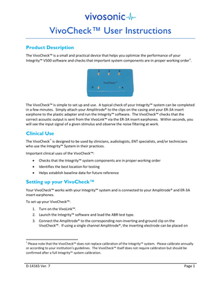
VivoCheck™ User Instructions Product Description The VivoCheck™ is a small and practical device that helps you optimize the performance of your Integrity™ V500 software and checks that important system components are in proper working order 1.
The VivoCheck™ is simple to set up and use. A typical check of your Integrity™ system can be completed in a few minutes. Simply attach your Amplitrode® to the clips on the casing and your ER-3A insert earphone to the plastic adapter and run the Integrity™ software. The VivoCheck™ checks that the correct acoustic output is sent from the VivoLink™ via the ER-3A insert earphones. Within seconds, you will see the input signal of a given stimulus and observe the noise filtering at work.
Clinical Use The VivoCheck™ is designed to be used by clinicians, audiologists, ENT specialists, and/or technicians who use the Integrity™ System in their practices. Important clinical uses of the VivoCheck™: •
Checks that the Integrity™ system components are in proper working order
•
Identifies the best location for testing
•
Helps establish baseline data for future reference
Setting up your VivoCheck™ Your VivoCheck™ works with your Integrity™ system and is connected to your Amplitrode® and ER-3A insert earphones. To set up your VivoCheck™: 1. Turn on the VivoLink™. 2. Launch the Integrity™ software and load the ABR test type. 3. Connect the Amplitrode® to the corresponding non-inverting and ground clip on the VivoCheck™. If using a single channel Amplitrode®, the inverting electrode can be placed on
1
Please note that the VivoCheck™ does not replace calibration of the Integrity™ system. Please calibrate annually or according to your institution’s guidelines. The VivoCheck™ itself does not require calibration but should be confirmed after a full Integrity™ system calibration.
D-14165 Ver. 7
Page 1
either the ‘2’ snap or the ‘1’ snap. If using a dual channel Amplitrode®, both inverting electrodes are placed on the corresponding snaps. 4. Remove the white front tube adapter from the end of the right (red) ear tubing or left (blue) ear tubing of the ER-3A insert earphones and store in a safe location.
Remove the front tube adapter
5. Fit the tubing over the small white plastic tip protruding from the casing of the VivoCheck™ box.
ER-3A earphones and single channel and dual channel Amplitrodes attached to the VivoCheckTM
6. The Electrode Contact indicators on the Integrity™ test screen should be green when the Amplitrode® is connected.
Single and dual channel electrode contact indicators
Checking your Integrity™ System The VivoCheck™ provides these primary checks of your Integrity™ system: •
Checks that the correct signal is sent from the VivoLink™ through the ER-3A insert earphones. This can be done via visual observation by looking at the shape of the waveform as well as determining the peak-to-peak amplitude of the waveform.
•
Tests the Amplitrode®. Provides feedback via the Electrode Contact indicators on the Test screen.
•
Verifies the performance of the Integrity™ software and the SOAP-Kalman™ algorithm. Displays changing waveform morphology as noise is filtered from the signal.
To check your Integrity™ system: 1. Set up your VivoCheck™. 2. Launch the Integrity™ software and load the ABR/ECochG test type. 3. Select the protocol ‘ABR air-conducted 1000 Hz tone-burst 27.5’ and change the stimulus level to 75 dB nHL. You can also use the ‘VivoCheck protocol’, if available. 4. Ensure the polarity is set to Rarefaction. D-14165 Ver. 7
Page 2
5. If the right (red) tubing is attached to the VivoCheck™, click the Right Ear button in the Integrity™ test screen. If the left (blue) tubing is attached, click the Left Ear button. 6. Press ‘Start’ and ensure that the EEG scale is within ±15 μV and is as flat as possible. It may be necessary to move both the VivoCheck™ and VivoLink™ away from the laptop or powerlines to achieve this scale.
Acceptable EEG amplitudes reflecting electromagnetic noise detected by the VivoCheck™ with single and dual channel systems
7. Once the tone-burst waveform appears, increase the y-axis scale so that the entire waveform is visible within the graph.
Increase the y-axis scale to view the entire tone-burst waveform
Watch the SOAP-Kalman™ algorithm clean the signal, filtering unwanted noise and artifacts. In an area with low electromagnetic noise, it should not require more than approximately 200 Noise Adjusted Sweeps for a clean signal to appear. 8. Place the wave V marker on the highest peak and the wave V' marker on the lowest trough.
Single and dual channel tone-burst waveforms with V and V' markers to indicate the peak to peak amplitude
9. Verify that the V-V' value in the Integrity™ Test Conditions table is within the range specified on the back of your VivoCheck™ for the specific type of Amplitrode® you’re testing. This value indicates that the correct stimulus signal is being sent from the VivoLink™ to the ER-3A at a hearing level of 75 dB nHL. 10. Repeat steps 5 – 9 to test the ER-3A tubing for the other ear. 11. If amplitude values are not within the given range, confirm that the correct protocol, stimulus level and ear are being tested. Contact Vivosonic Customer Support if values remain out of range.
D-14165 Ver. 7
Page 3
Identifying the Best Location for Testing Your Integrity™ system’s advanced technologies enable reliable testing in less than ideal conditions. However, it is recommended that testing be conducted in a location with minimal electromagnetic interference. This enables faster test times and cleaner signals. The VivoCheck™ can help you identify the best location for testing by providing an indication of the electromagnetic interference in the immediate environment. To identify the best location for testing: 1. Place your Integrity™ system in the desired location for testing. 2. Connect your VivoCheck™ to your Integrity™ system. 3. Select the ‘ABR air-conducted 1000 Hz tone-burst 27.5’ protocol or the ‘VivoCheck’ protocol, if available and observe the EEG indicator and waveform. •
EEG amplitudes that are within the ±15 μV range indicate acceptable levels of electromagnetic noise in the environment.
•
If the EEG displays an area with electromagnetic noise that is outside of the ±15 μV range, it may take the SOAP™ algorithm longer to scrub out the noise. Testing in such an environment is not recommended, as the test will take significantly longer. 4. Repeat steps 1-3 to find a location with minimal electromagnetic interference.
Indicates low electromagnetic noise (best for testing)
Indicates high electromagnetic noise
Determining Baseline Data It is of value to collect a baseline waveform from the VivoCheck™ in your testing location. This baseline waveform will enable you to compare noise in the environment if you suspect conditions have changed and are affecting your measurements. 1. Set up your VivoCheck™ and Integrity™ system. 2. Run the ‘ABR air-conducted 1000 Hz tone-burst 27.5’ protocol at 75 dB nHL. Or select the ‘VivoCheck’ protocol, if available. 3. Take note of your system set up as well as the general EEG amplitude showing the level of electromagnetic noise in the environment. A good way to do this would be to take a screenshot of your EEG and save it on the computer.
D-14165 Ver. 7
Page 4
4. Attach a comment to your waveform indicating the amplitude and scale of the EEG present while testing. Save the tone-burst waveform.
5. The saved EEG data and tone-burst waveform can be used for future reference to determine whether ambient electrical noise in this location has changed. In noisy environments, it will take longer for the Integrity™ software to filter the noise. This is illustrated in the following figures.
Baseline data -collected in a low noise environment, shows a clean waveform obtained within 200 Noise Adusted Sweeps and an EEG with amplitudes of 2-3 μV.
Data collected at a later date -significantly noisier than the baseline data, therefore it will take longer to achieve a clean tone-burst waveform. ABR testing in these conditions is not recommended.
Calculating the Tone-Burst Frequency An additional benefit to using the VivoCheck™ is the ability to confirm the frequency of the tone-burst signal. 1. Set up your VivoCheck™ and Integrity™ system. 2. Run the ‘ABR air-conducted 1000 Hz tone-burst 27.5’ protocol at 75 dB nHL, or select the ‘VivoCheck’ protocol, if available. 3. Place a wave III marker on the first peak of the waveform and a wave V marker on the second peak of the waveform.
Tone-burst waveform with wave III and wave V markers placed
D-14165 Ver. 7
Page 5
4. In the Test Conditions table, there is a column indicating the latency for III-V. This value represents the frequency of the tone-burst waveform within ± 0.08 ms.
III-V indicates a period of 0.99 ms which corresponds to a frequency of approximately 1000 Hz
Impedance Values The VivoCheck™ has a built-in impedance mismatch of 6 kΩ. However, in areas of high noise, this impedance value may increase or decrease. The system should be placed in a less noisy location to achieve best results. Integrity™ versions 5.2.2 to 8.0
Integrity™ versions 8.1 and higher
Impedance mismatch = 6 ± 1 kΩ in an ideal environment
Ground: 5 ± 3 kΩ Non-Inverting: 1 ± 1 kΩ Inverting 1: 6 ± 1 kΩ Inverting 2: 6 ± 1 kΩ (dual channel Amplitrode) in an ideal environment
D-14165 Ver. 7
Page 6