Wangara
ARJOHUNTLEIGH Pressure Redistributing Mattress Overlay
ARJOHUNTLEIGH AUTO LOGIC Series Service Manual Issue 4 May 2013
Service Manual
204 Pages
Preview
Page 1
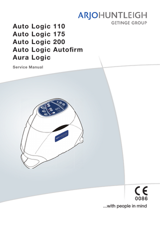
Auto Logic 110 Auto Logic 175 Auto Logic 200 Auto Logic Autofirm Aura Logic Service Manual
0086 ...with people in mind
Auto Logic 110/175/200, Autofirm & Aura Logic Service Manual
Service Bulletins
Service Bulletins Incorporated Bulletin
Date incorporated
Content
SERB004
Autologic software VAB
Oct 2011
SERB005
Autologic software V1
Oct 2011
SERB014
Tubeset Assembly - change to spring and tubeset material
Oct 2011
SERB016
Communicator Software Restrictions
Mar 2012
SERB018
Addition of Test Port and Pressure Changes
Oct 2011
SERB020
Software Upgrade to V2.05
Oct 2011
SERB026
Change to Inflation Test Parameters
Oct 2011
SERB031
New AUTO Logic 175 mattress. Change to AUTO Logic 200 B-Pad
Oct 2011
SERB037
Introduction of new AUTO Logic PCB (630140)
Oct 2011
SERB049
Pump Front and Rear Case Part Changes
Oct 2011
SERB053
Battery Pack - Reset/Status Latch
Oct 2011
FSN001/ 2012/T&PP
Device Modification - Re-calibration of Pumps Pressure Transducer
Mar 2012
SERB064
Battery Pack - Serviceability Update
May 2013
Issue 4 May 2013
SER0006
Amendment Record Page (i)
Service Bulletins
Amendment Record Page (ii)
Auto Logic 110/175/200, Autofirm & Aura Logic Service Manual
SER0006
Issue 4 May 2013
Auto Logic 110/175/200, Autofirm & Aura Logic Service Manual
Contents
CONTENTS CHAPTER 1 Introduction... 1 About This Manual... 1 Numbering and Cross-Referencing in this Manual... 1 Warnings, Cautions and Notes... 1 General Warnings... 1 General... 2 Regulatory... 2 Precautions... 2 Electromagnetic Compatibility (EMC)... 2 Environmental Protection... 2 Design Policy and Copyright... 2 About the Auto Logic System... 2 Auto Logic Front and Rear Case Changes 2010... 4 Pump (Refer to Figure 2)... 6 Auto Logic 110 Mattress Overlay (Refer to Figure 3)... 7 Auto Logic 175 & 200 Mattress Replacement (Refer to Figure 3)... 7 Aura Logic Seat Cushion (Refer to Figure 5)... 8 Electric and Mattress Pneumatic Diagrams... 9 Operating Principle... 11 Pump... 11 Alarms and Indicators (Refer to Figure 9)... 12 Replacement Sub-Assemblies... 12 Pressure Transducer Calibration... 13 Mattress Overlay Core... 14 Mattress Base Pad... 14 Seat Cushion... 15 Auto-Recognition System... 16 System Start Up Sequence (Refer to Figure 9)... 16
CHAPTER 2 Troubleshooting... 17 Controls, Alarms and Indicators (Refer to Figure 12)... 17 Diagnosing Faults... 17 Diagnosing Faults... 18 Diagnosing Faults using the Event Logs on the Communicator Software... 20 Check for Self Set Technology (SST) Errors... 27
Issue 4 May 2013
SER0006
Page (iii)
Contents
Auto Logic 110/175/200, Autofirm & Aura Logic Service Manual
Check if the Pump is due for a Routine Service... 28 Check and Clear SST Errors... 28 Checking and Clearing SST Errors on pump units with early 630400 PCB and all Autofirm pumps... 28 Diagnosing Pump Faults using the Built-In Self-Test Routine with no PC... 31 Checking the Status and Diagnosing Faults on the Intelligent Battery Pack... 33 General... 33 To Check the Battery Pack Status (Refer to Figures 16 and 17)... 34 Battery Pack “Conditioning” Fault... 35 Battery Pack Disposal... 35
CHAPTER 3 Maintenance... 37 Pump Service... 37 Pump Maintenance Checks... 38 Mattress Replacement and Mattress Overlay Service... 38 Mattress Replacement and Mattress Overlay Maintenance Checks... 39 Seat Cushion Service... 39 Seat Cushion Maintenance Checks... 39
... 40 CHAPTER 4 Testing... 41 Pump Control Panel... 41 Test Equipment... 41 Checking the Basic System Operation... 42 Checking the Pump Pressures without a Computer... 42 Connecting the Pump to a Personal Computer (PC)... 46 Laptop / Desktop PC... 46 Computer Communication... 46 Installing the USB to RS232 Adaptor... 46 Running the Communicator Software... 49 Executing Commands and Test Sequences on the Command Menu... 54 Executing Single Commands... 54 Executing Test Sequences... 55 Operating the Pump from a PC via the IR Interface Module... 56 Closing the Communicator Software... 57 Checking the Pump Pressures and Free Flows with a Computer... 58 Checking the Calibration of the Pressure Transducer... 60
Page (iv)
SER0006
Issue 4 May 2013
Auto Logic 110/175/200, Autofirm & Aura Logic Service Manual
Contents
Re-Calibrating the Pressure Transducer and Verifying the Pressures (Pumps Installed With 630400 PCB Assembly)... 62 Checking the Software Version of the Pump... 62 Re-Calibrating the Pressure Transducer... 62 Verifying the Pressures... 64 Making Fine Adjustments to the Transducer Calibration... 64 End of Test... 65 Re-Calibrating the Pressure Transducer and Verifying the Pressures (Pumps Installed With 630140 or 654140 PCB Assemblies)... 65 Setting up the Pressure Source Pump... 65 Setting the Air Pressure on the Pressure Source Pump... 65 Re-calibrating the Field Service Pump with 630140 or 654140 PCB Assemblies... 67 Making Fine Adjustments to the Transducer Calibration... 68 End of Test... 68 Setting the Service Hours on the Pump... 69 Checking the Sounder and Power Fail Alarm LED Indicators... 70 The procedure applies to all pumps:... 70 Setting Up a New Control PCB Assembly... 70 Setting the GMT Time and Date... 71 Pressure Logging using the Communicator Software (if applicable)... 71 Electrical Safety Testing... 74 Electrical Safety Checks - Class II (Double Insulated)... 74 Insulation Resistance Test... 74 Dielectric Strength Test (Flash Test)... 74 Leakage Circuit Test (USA)... 74 Inflation Test of the Mattress Replacement, Overlay or Seat Cushion... 75 Test Procedure... 75 Pneumatic Test For Cell in Cell Static Line... 76
CHAPTER 5 Pump Repair... 77 General... 77 Pump Repair to Testing Requirements... 77 Removing the Mains/Power Cordset... 79 Installing the Mains/Power Cordset... 79 Removing the Air Inlet Filter... 79 Installing the Air Inlet Filter... 79 Removing the Rear Case... 81 Installing the Rear Case... 81 Removing the Hooks... 83
Issue 4 May 2013
SER0006
Page (v)
Contents
Auto Logic 110/175/200, Autofirm & Aura Logic Service Manual
Installing the Hooks... 83 Removing the Manifold Assembly... 85 Installing the Manifold Assembly... 85 Replacing the RFID (Radio Frequency Identification) Coil Antenna... 89 Removing the Silencer Bag Assembly... 90 Installing the Silencer Bag Assembly... 90 Replacing the O-Rings on the Manifold Assembly... 91 Removing the Compressor Assembly and Mounting Bracket... 93 Installing the Compressor Assembly and Mounting Bracket... 93 Removing the Compressor Assembly from the Mounting Bracket... 95 Installing the Compressor Assembly onto the Mounting Bracket... 95 Replacing the Compressor Assembly... 97 Removing the Power Supply PCB (Printed Circuit Board) Assembly... 99 Installing the Power Supply PCB (Printed Circuit Board) Assembly... 99 Removing the Control PCB (Printed Circuit Board) Assembly... 101 Installing the Control PCB (Printed Circuit Board) Assembly... 101 Removing the PCB Mounting Pillars... 101 Installing the PCB Mounting Pillars... 101 Replacing the Battery on the Control PCB Assembly... 102 Pump Labels... 104 Replacing the Mains/Power Fuses on the Power Supply PCB Assembly... 106 Replacing the Air Inlet Filter on the Compressor Assembly... 106 Removing the Membrane Label... 108 Installing the Membrane Label... 108 Replacing the Rear Case... 110 Replacing the old style ‘Huntleigh Healthcare’ Front Case... 112 Replacing Both Pump Casings... 115 Mains Cable Information... 122
CHAPTER 6 Mattress Repair...123 General... 123 Removing the Top Cover Assembly... 124 Installing the Top Cover Assembly... 124 Removing a Cell Assembly... 127 Installing a Cell Assembly... 129 Removing the Manifold Tube Assembly... 131 Installing the Manifold Tube Assembly... 131 Replacing/Fitting Test Port Assembly To Static Cell-in-Cell Line... 133
Page (vi)
SER0006
Issue 4 May 2013
Auto Logic 110/175/200, Autofirm & Aura Logic Service Manual
Contents
Replacing the Non-Return Valves... 135 Replacing the Partial Non-Return Valve Assembly at the Head End of the Mattress . . . 135 Replacing the Non-Return Valve at the Foot End of the Mattress... 135 Removing the Low-Air-Loss (LAL) Patch Tube Assembly... 136 Installing the Low-Air-Loss (LAL) Patch Tube Assembly... 136 Separating the Mattress Overlay from the Mattress Base Pad... 138 Attaching the Mattress Overlay to the Mattress Base Pad... 139 Removing the Pump Tubeset Assembly... 141 Installing the Pump Tubeset Assembly... 141 Removing the CPR Assembly... 142 Installing the CPR Assembly... 142 Removing the Manifold Connector Assembly from the Mattress Overlay... 142 Installing the Manifold Connector Assembly onto the Mattress Overlay... 142 Removing a Retaining Strap Assembly... 143 Installing a Retaining Strap Assembly... 143 Replacing the Base Sheet Assembly... 144 Mattress Test Port (July 2004 Onward)... 145 Removing the Manifold Connector Assembly from the Mattress Base Pad... 147 Installing the Manifold Connector Assembly onto the Mattress Base Pad... 147 Replacing the Draw Latches on the Manifold Connector Assembly... 147 Removing a Retaining Strap Assembly... 149 Installing a Retaining Strap Assembly... 149 Replacing the Base Pad Sub-Assembly... 149 Interchangeability of New and Old Auto Logic 200 Spare Parts... 150 Press Stud Replacement... 151
CHAPTER 7 Seat Cushion Repair... 153 General... 153 Removing the Top Cover Assembly... 153 Installing the Top Cover Assembly... 153 Removing the Welded Cell Assembly... 155 Installing the Welded Cell Assembly... 155 Removing the Pump Tubeset Assembly... 156 Installing the Pump Tubeset Assembly... 156 Removing a Retaining Strap Assembly... 156 Installing a Retaining Strap Assembly... 156 Replacing the Base Assembly... 158
Issue 4 May 2013
SER0006
Page (vii)
Contents
Auto Logic 110/175/200, Autofirm & Aura Logic Service Manual
CHAPTER 8 Intelligent Battery Pack Assembly...159 General... 159 Installing and Removing the Battery Pack... 159 Checking the Status of the Battery Pack... 160 Battery Pack Status Label... 160 To Check the Battery Pack Status (Refer to Figures 92 and 93)... 160 Battery Pack Storage... 160 Battery Pack Disposal... 160 Recharging the Battery Pack... 161 Replacing the Battery Pack Reset/Status Latch... 163 Testing the Battery Pack... 164
CHAPTER 9 Communicator Software...167 General... 167 Auto-Installing the Communicator Software... 168 Manually Installing the Communicator Software... 171 Running the Communicator Software... 172
CHAPTER 10 Technical Specification...173 Pump... 173 Environmental Information... 174 Accessories... 174 Mattress... 175 Mattress Size Information... 175 Seat... 176 Cleaning Symbols... 176 Cover Specification... 177
CHAPTER 11 Parts List...181 General... 181 Overall Assembly Parts List... 181 Pump Assembly Parts List... 183 Mattress Overlay Assembly Parts List... 186 Mattress Base Pad Assembly Parts List... 188 Seat Cushion Assembly Parts List... 188
Page (viii)
SER0006
Issue 4 May 2013
Auto Logic 110/175/200, Autofirm & Aura Logic Service Manual
Contents
Intelligent Battery Pack Assembly... 189 Test Equipment... 189
CHAPTER 12 Service Contact Details... 191
Issue 4 May 2013
SER0006
Page (ix)
Contents
Page (x)
Auto Logic 110/175/200, Autofirm & Aura Logic Service Manual
SER0006
Issue 4 May 2013
Auto Logic 110/175/200, Autofirm & Aura Logic Service Manual
Introduction
CHAPTER 1 INTRODUCTION 1
About This Manual
ArjoHuntleigh strongly recommend that their equipment is only serviced by trained personnel and provide courses for customers who wish to become licensed to service their own equipment. In no event will ArjoHuntleigh be responsible for any service performed by customers or third parties. This manual contains information on maintenance, servicing, repair, troubleshooting and testing for the Auto Logic® 110, Auto Logic® 175, Auto Logic® 200, Aura Logic® Auto Logic® Autofirm and systems which comprise a pump and either a mattress overlay, mattress replacement or a seat cushion. You must read and understand this manual before attempting to service or repair the equipment. In addition to the service details contained within this manual, service engineers should also ensure that any work is also in compliance with their national legislation relating to maintenance and repair of electrical medical devices.
Numbering and Cross-Referencing in this Manual For all chapters in this manual: • Chapter page numbering is continuous. Section and paragraph numbering re-start at “1” in each chapter. • Page, figure and table numbering continue from the previous chapter. • Cross-references which include a chapter number (and/or chapter title) refer to text in a different chapter. Cross-references which do NOT include any chapter number (or chapter title) refer to text within the same chapter.
Warnings, Cautions and Notes WARNINGS given in this manual identify possible hazards in procedures or conditions which, if not correctly followed, could result in death, injury or other serious adverse reactions. CAUTIONS given in this manual identify possible hazards in procedures or conditions which, if not correctly followed, could result in equipment failure or damage. Notes given in this manual are used to explain or amplify a procedure or condition.
General Warnings WARNING: BEFORE PERFORMING ANY SERVICE OR MAINTENANCE PROCEDURES, ENSURE THAT THE EQUIPMENT HAS BEEN ADEQUATELY DECONTAMINATED. WARNING: VOLTAGES IN EXCESS OF 30 VOLTS RMS OR 50 VOLTS DC CAN, IN CERTAIN CIRCUMSTANCES, BE LETHAL. WHEN WORKING ON EQUIPMENT REQUIRING EXPOSURE TO LIVE, UNPROTECTED CONDUCTORS WHERE SUCH VOLTAGES ARE PRESENT, EXTREME CARE MUST BE EXERCISED. WARNING: BEFORE DISMANTLING THE PUMP, MAKE SURE IT HAS BEEN ISOLATED FROM THE MAINS/POWER SUPPLY BY REMOVING THE MAINS/POWER PLUG FROM THE WALL SOCKET. WARNING: STATIC SENSITIVE DEVICES. ELECTROSTATIC DISCHARGE CAN SERIOUSLY DAMAGE THE PCB ASSEMBLIES. THIS PUMP SHOULD ONLY BE OPENED BY PERSONNEL TRAINED IN ESD METHODS AND WITH APPROPRIATE EQUIPMENT AND ANTI-STATIC PROTECTION.
Issue 4 May 2013
SER0006
Chap 1 Page 1
Introduction
2
Auto Logic 110/175/200, Autofirm & Aura Logic Service Manual
General
Regulatory The Auto Logic system has been designed to comply with regulatory safety standards including: • EN60601-1:1990/A13:1996 and IEC 60601-1:1988/A2:1995 • UL60601-1, UL2601-1 and CAN/CSA C22.2 No. 601.1-M90 • EN60601-1:2006 and IEC 60601-1:2005 • AAMI/ANSI ES60601-1:2006 and CAN/CSA C22.2 No.60601.1(2008)
Precautions For your own safety and the safety of the equipment, always take the following precautions: • Do not expose the system, especially the mattress, to naked flames, such as cigarettes, etc. • Do not use or store the system in direct sunlight. • Do not use phenol-based solutions to clean the system. • Make sure the system is clean and dry before use or storage. • Never use sharp objects or electrically heated under blankets on or under the system. • Store the pump and mattress or seat cushion in protective bags.
Electromagnetic Compatibility (EMC) This product complies with the requirements of applicable EMC Standards. Medical electrical equipment needs special precautions regarding EMC and needs to be installed in accordance with the following instructions: • The use of accessories not specified by the manufacturer may result in increased emissions by, or decreased immunity of, the equipment, affecting its performance. • Portable and mobile radio frequency (RF) communications equipment (e.g. mobile/cell phones) can affect medical electrical equipment. • If this equipment needs to be used adjacent to other electrical equipment, normal operation must be confirmed before use.
Environmental Protection Incorrect disposal of this equipment and its component parts, particularly batteries or other electrical components, may produce substances that are hazardous to the environment. To minimise these hazards, contact ArjoHuntleigh for information on correct disposal.
Design Policy and Copyright ® and ™ are trademarks belonging to the ArjoHuntleigh group of companies. As our policy is one of
continuous improvement, we reserve the right to modify designs without prior notice. The content of this publication may not be copied either whole or in part without the consent of ArjoHuntleigh. © ArjoHuntleigh 2012
3
About the Auto Logic System
The Auto Logic 110, Auto Logic 175, Auto Logic 200 and Aura Logic and Auto Logic Autofirm systems are automatic alternating pressure relief systems to aid the prevention, treatment and management of pressure ulcers: • •
•
The Auto Logic 110 system comprises a pump and a mattress overlay. The mattress overlay is designed to be placed on top of any standard mattress. The Auto Logic 175 system comprises a pump and a mattress replacement. The mattress replacement is designed to replace the standard mattress on a bed, and comprises a mattress overlay on top of a foam mattress underlay. The mattress overlay is similar to that on the Auto Logic 110 system, but has two extra zips to secure the mattress base pad to it. The Auto Logic 200 system comprises a pump and a mattress replacement. The mattress replacement is designed to replace the standard mattress on a bed, and comprises a mattress
Chap 1 Page 2
SER0006
Issue 4 May 2013
Auto Logic 110/175/200, Autofirm & Aura Logic Service Manual
• •
Introduction
overlay on top of an air filled sub-mattress. The mattress overlay is similar to that on the Auto Logic 110 system, but has two extra zips to secure the mattress base pad to it. The Aura Logic system comprises a pump and a seat cushion. The seat cushion is designed to be placed on top of any standard chair. The Auto Logic Autofirm is a standard Auto Logic with the addition of an ‘Autofirm’ function. Once activated, Autofirm creates a temporary firm surface to allow nursing procedures to be performed. Autofirm lasts 15 minutes, after which the pump will default back to the previous setting. The Auto Logic Autofirm runs the standard Auto Logic mattresses, which are as follows: • Auto Logic 110 Mattress Overlay • Auto Logic 175 Mattress Replacement • Auto Logic 200 Mattress Replacement Note: Autofirm will not function on the Aura Logic system. Note: The Auto Logic Autofirm was originally a special pump variant restricted to certain markets, but the Autofirm function is now incorporated in all Auto Logic 110, 175 and 200 mattress systems.
The difference between the Auto Logic and Auto Logic Autofirm are: • • •
Control PCB Software Pump Membrane Label
All systems are are designed to operate in either Active (Alternating) mode, which continuously changes the tissue pressure points providing a high degree of pressure relief, or Reactive (Constant Lower Pressure) (CLP) mode, which provides a constant lower pressure reduction and is used when a moving surface is contra-indicated for the patient.
Issue 4 May 2013
SER0006
Chap 1 Page 3
Introduction
Auto Logic 110/175/200, Autofirm & Aura Logic Service Manual
Auto Logic Front and Rear Case Changes 2010 Note: These variations do not apply to Auto Logic Autofirm which is made only with the new style case and unique membrane label. In 2010 the front case of the Auto Logic pump was updated. The rear case, while not changing internally also required an update, which has resulted in the updated pump casings NOT being compatible with the old pump cases. If replaced, the front and rear case parts must be replaced as a pair. Some illustrations in this manual show detail of the old pump casing, however where procedures are affected by the differences, they are highlighted and detailed accordingly. The quickest way to identify the case type is to look for the connector for the optional patient handset which is only fitted to the old style front case. The full list of differences between the old front case and the updated front case is below: Table 1 - Front Case Differences Applicable to 630320
Change Made to 630570
Patient Handset Grommet
Removed. (Handset no longer available).
Embossed Huntleigh “H”
Removed.
Recess support for Membrane label
This area is now a solid part of the new case Moulding (slot for membrane cable still exists).
Membrane Label: 630448 or LAB313 Note: If label replacement is required, always fit LAB392 (Refer to Figure 5).
Fitted with LAB402.
Strengthening Aid: 630399
No longer required with new case Moulding.
Insert Membrane Support: 630328
No longer required with new case Moulding.
Auto Logic Badge: 630398
ArjoHuntleigh Gel Pad Badge: PKG830.
Chap 1 Page 4
SER0006
Issue 4 May 2013
Auto Logic 110/175/200, Autofirm & Aura Logic Service Manual
Introduction
H
630448 (discontinued) “H” Branding
LAB313 (discontinued) Plain
LAB392 “Auto logic” Branding without Autofirm button
LAB402 (current) “Auto Logic” Branding with Autofirm button
LAB316 (discontinued) Danish model with Autofirm button
Figure 1 - Auto Logic Membrane Label Differences
Power and Alarm Indicators
H
Control Panel
Mains/Power Cordset
Hanging Brackets Rear view
Front view Figure 2 - Pump (new style case)
Issue 4 May 2013
SER0006
Chap 1 Page 5
Introduction
Auto Logic 110/175/200, Autofirm & Aura Logic Service Manual
Top Cover Head End of Mattress
Mattress Overlay (Core) Cable Management
Cells
CPR Unit
Corner Straps
Pneumatic Connection Pump Connector
Tubeset
Mattress Base Pad
Securing Straps Figure 3 - Mattress Overlay and Replacement
Pump (Refer to Figure 2) The pump provides a dynamic system of inflating the support surface underneath the patient, cycling every 10 minutes to produce periods of pressure relief for the whole body. The single compressor pump has microprocessor-aided control and alarm functions, and has LED indications on the front case of the pump and the control panel on top of the pump. An optional intelligent battery pack is available which allows the pump to be used independently of the mains/power supply. The battery pack slides onto the base of the pump, and recharges itself when the pump is operating from the mains/power supply. A patient handset (no longer supplied) was previously available as an optional extra. Pumps with this facility are identifiable by a socket located on the left-hand side of the pump when viewed from the front. The handset gives the patient control over the comfort settings of the mattress and also allows them to mute the alarm. The Auto Logic systems do not have a pressure sensor pad in the mattress. Instead, the pump incorporates Self Set Technology (SST), which adjusts the air pressure within the mattress every 10 minutes in Active (Alternating) mode and 20 minutes in Reactive (Constant Lower Pressure) (CLP) mode to suit the Body Mass Index (BMI) and position of the patient. Both support systems can be used on standard hospital and domestic beds.
Chap 1 Page 6
SER0006
Issue 4 May 2013
Auto Logic 110/175/200, Autofirm & Aura Logic Service Manual
Introduction
Auto Logic 110 Mattress Overlay (Refer to Figure 3) The mattress overlay comprises a mattress core of 20 individual cells which support the patient (Refer to Figure 4). 17 of the cells inflate alternately, and the remaining three are static cells to support the patient’s head. The 10 light blue alternating cells in the centre of the mattress core incorporate two small cells at either end of the main cell. These “cells-in-cell” are kept at a constant pressure and help the transfer of patients on and off the bed by keeping the edges of the mattress firm. The remaining 10 cells (five at each end of the mattress) are dark blue. The mattress core incorporates a low-air-loss patch under the cells to provide a constant bleed of air for additional patient comfort. Should the patient experience cardiac arrest, a CPR (Cardio-Pulmonary Resuscitation) unit is positioned at the head end of the mattress core, to allow the mattress to rapidly deflate. The mattress overlay is permanently connected to the pump via a 3-way tubeset. This tubeset has a 3way pneumatic connection which incorporates a flexible, compact anti-kink tube which is resistant to crushing and any subsequent obstruction in air flow. Dark Blue
Dark Blue
“Cell-in-Cell” (Light Blue)
Foot End Cell Numbers
Head End 20 19 18 17 16 15 14 13 12 11 10 9 8 7
6
17 Alternating Cells
5 4 3 2 1 3 Static Cells
Figure 4 - Mattress Overlay Cell Numbering To switch to transport mode, disconnect the tubeset from the pump. This will automatically seal the mattress so that air is not exhausted. It also cross-connects the cells to create an even pressure throughout. To resume normal operation, reconnect the tubeset to the pump. The mattress overlay is enclosed in a polyurethane-coated fabric cover, with water-resistant, vapour permeable and two-way stretch properties. These assist with patient repositioning requirements and enhance comfort, while protecting the mattress interior from contamination. The overlay is simple to clean in situ, but can also be quickly unzipped and completely removed for thorough cleaning. The zips are protected by flaps to prevent the ingress of contaminants. The base cover for the mattress overlay has four adjustable corner retention straps which slide under the corners of the base mattress. To keep the mains/power cable tidy and protect it from damage, a cable management flap secured by pop studs runs down the length of the mattress overlay, on the opposite side to the pump tubeset and CPR unit.
Auto Logic 175 & 200 Mattress Replacement (Refer to Figure 3) The Auto Logic 200 mattress replacement comprises a mattress overlay on top of an air filled submattress. The mattress overlay is similar to the Auto Logic 110 Mattress Overlay, but has two extra zips to secure the air filled sub-mattress to it. There is also a pneumatic connection between the mattress overlay and the air filled sub-mattress. The base pad has eight adjustable straps on the underside to attach it to the bed frame. The air filled sub-mattress comprises a main body zone and a perimeter cell zone. Both zones are fed directly from the air supply in the mattress overlay and are kept at a constant pressure. The main body zone is at the same static pressure as the head cells in the mattress overlay while the perimeter cell zone is at the higher static pressure of the cell-in-cells in the mattress overlay. The air in the air filled sub-mattress is evacuated via the CPR unit in the mattress overlay, should a cardiac arrest occur.
Issue 4 May 2013
SER0006
Chap 1 Page 7
Introduction
Auto Logic 110/175/200, Autofirm & Aura Logic Service Manual
The Auto Logic 175 operates in the same way as the Auto Logic 200 above, however the air filled submattress is replaced with a foam mattress underlay. The mattress base pad also has a cable management flap secured by pop studs, on the opposite side to the pump tubeset and CPR unit.
Aura Logic Seat Cushion (Refer to Figure 5) The seat cushion comprises seven alternating cells which are connected to the pump via a 2-way tubeset (there is no static feed in the seat cushion). The seven cells are manufactured as a single welded assembly, which is enclosed by a zipped cover. The base cover has two fixing straps to attach it to the chair. There are two small dump valves on the underside of the base cover which are used to release the air inside the seat cushion in an emergency or for storage. Base Cover
©
lo
gi
c
Cell Assembly Dump Valves on underside of Case Cover
Base Cover
2-way Tubeset
Fixing Straps
Figure 5 - Seat Cushion
Chap 1 Page 8
SER0006
Issue 4 May 2013
Auto Logic 110/175/200, Autofirm & Aura Logic Service Manual
Introduction
Electric and Mattress Pneumatic Diagrams
Membrane Cable
Con 14 (Microswitch)
Membrane Control Panel
Con 1
Con 15
Rechargeable Battery Con 6 Patient Handset (no longer fitted)
Con 4 (Stepper Motor)
Con 12
Con 8 (Coil)
Control PCB Assembly Ribbon Cable
RFID Coil Antenna
Control Board Connector
Con 3
FS2
FS1
Manifold Assembly Fuses Con 6 Con 7
Con 2
Mains/Power Cordset
Power Supply PCB Assembly Battery Pack Connector
7 8
4 3
5 6
2 1
Compressor Assembly
Figure 6 - Electrical Circuit Diagram
Issue 4 May 2013
SER0006
Chap 1 Page 9