WelchAllyn
LS 200 Procedure Light Owners Manual Rev H
Owners Manual
84 Pages
Preview
Page 1
Lighting LS 200 Service Manual
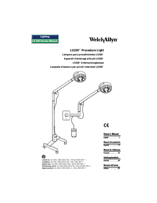
LS200™ Procedure Light Lámpara para procedimientos LS200™ Appareil d’éclairage articulé LS200™ LS200™ Untersuchungslampe Lampada d’esame e per piccoli interventi LS200™
Owner’s Manual English...1 Manual del propietario Español...17 Manuel de l’utilisateur Français...33 Anleitungshandbuch Listed to: UL 544, CSA C22.2 No. 125 and IEC 601-1 Listados: UL 544, CSA C22.2 No. 125 y IEC 601-1 Agréé par: UL 544, CSA C22.2 No. 125 et IEC 601-1 Zulassung nach: UL 544 CSA C22.2 Nr. 125 und IEC 601-1 Approvazioni: UL 544, CSA C22.2 n. 125 e IEC 601-1
Deutsch...49 Manuale dell’utente Italiano...65
Thank you for purchasing the Welch Allyn ® LS200™ Procedure Light, designed by a leading worldwide manufacturer of illuminated diagnostic instrumentation. By following the use and care guidelines given in this manual, you will be rewarded with years of dependable, trouble-free service from your new LS200 Procedure Light. Read these instructions thoroughly before use.
!
WARNING
All users of this procedure light should be thoroughly trained in the medical procedures appropriate to the equipment. Furthermore, they should read and understand the instructions for all other equipment used in conjunction with the LS200™ Procedure Light. Lamps are extremely bright. DO NOT stare directly into lamps when lit. DO NOT position luminaire in the upward direction with the lamps on.
! CAUTION Remove power cord from electrical outlet and allow lamps to cool before replacing (replace with Welch Allyn Lamp #06400 only). Accessible metal parts of this unit are electrically isolated from the grounding conductor of the supply cord. If grounding of the accessible parts is considered necessary, a separate grounding lead should be employed. To reduce the risk of electric shock, do not disassemble unit. Refer servicing to qualified service personnel.
!
CAUTION
Operation at closer than 12" (30.5 cm) for extended periods may result in erythema. The designed working distance is 24" (60 cm).
!
60cm
CAUTION
The switch on luminaire is NOT a mains switch. Transformer energizes when the light is plugged to mains.
!
DANGER
Risk of explosion if used in the presence of flammable anesthetics.
HOT SURFACE The bezel in front of the lamps may be hot. 1
TABLE OF CONTENTS Components ...3 Mounting...4 Mobile Stand Set-up ...4 Wall Mount Set-up ...5 Mounting to Wood Stud...5 Mounting to Concrete or Brick Wall...6 Transformer Mounting ...8 Operating Instructions ...8 Transport Instructions for Mobile Stand Unit ...8 Arm Adjustment ...9 Lamp Replacement ...9 Fuse Replacement ...11 Cleaning ...12 Maintenance and Repair ...12 Warranty ...12 Electrical Specifications ...13 Operation Environment...14 Troubleshooting Guide ...15
2
COMPONENTS
ARM/LUMINAIRE ASSEMBLY
WALL MOUNT
EXTENSION ARM (G) UNIVERSAL CONNECTOR (B)
TRANSFORMER
WALL MOUNT HARDWARE
POWER CORD (e)
MOBILE STAND HARDWARE POWER CORD CLIPS (D)
FLAT HEAD SCREW (b) ALLEN WRENCH
WOOD SCREWS CAP HEAD BOLT (F)
FLAT HEAD SCREW (b)
TRANSFORMER HARDWARE
ALLEN WRENCHES
POLE END (A)
MASONRY SCREWS
LOCK WASHER (f) TRANSFORMER MOUNTING SCREWS (C)
CONCRETE SCREWS
MOBILE STAND CASTER LOCKS
MOBILE STAND BASE
3
WOOD SCREWS
MOUNTING MOBILE STAND SET-UP 1. Remove stand base, pole and hardware kit from boxes. 2. Place stand base on floor with casters down and lock casters. 3. Insert pole end (A) into hole in base of mobile stand. 4. Rotate pole until it aligns with pin and drops into place. 5. Insert cap-head bolt (F) with lock washer (f) through stand cross member into pole and tighten with 1/4" Allen wrench. 6. Carefully remove LS200 arm/luminaire assembly from box. Hook transformer onto the factory installed mounting screws (C) on the pole and slide down until secure. 7. Place arm/luminaire assembly on pole by sliding universal connector (B) onto top end of the pole and align screw holes. (b)
(B)
8. Insert 0.5" (13mm) flathead screw (b) into hole on side of universal connector and tighten with 5/32" Allen wrench. 9. Push power cord attached to transformer into power cord clips (D) on pole, ensuring enough slack for full range (D) of arm motion. 10. Attach power cord (e) to transformer. 11. To lock casters, push down on the tab on the locking casters. (e)
12. Before moving the LS200 Procedure Light, refer to “Transport Instructions” on Page 8.
(C)
(A)
CASTER LOCKS (f) (F) ALIGN PIN IN MOBILE STAND WITH POLE END
4
WALL MOUNT SET-UP CAUTION: DO NOT mount into sheetrock. Must be mounted into stud. The LS200 Procedure Light arm is designed not to go beyond 90˚ and the working distance is 24" (60cm). To ensure proper placement on the wall, the top edge of the wall plate should be located 4" (10cm) above the working surface.
4" 4"
NOTE: Wall plate must be leveled using a carpenter’s level to ensure precise, drift-free movement.
Mounting to wood stud: 1. Remove wall mount assembly and hardware kit from box. 2. Select mounting location on a stud in the wall that is within 8' (2.4m) of electrical outlet. 3. Using wall plate as a template, place on selected location on wall, level plate and mark both holes. 4. Remove wall plate and drill pilot holes using 0.12" (3mm) drill bit. 5. Place wall plate on wall WOOD STUD and drive top 1.5" (3.8cm) wood screw halfway into LEVEL wood stud. 6. Align wall plate using a level and secure at bottom with 1.5" (3.8cm) wood screw. WOOD SCREW 7. Tighten top wood screw. 8. Prepare for transformer EXTENSION ARM (G) mounting by following “Transformer Mounting” instructions through step 4 on page 8.
5
9. Carefully remove LS200 arm/luminaire ARM/ LUMINAIRE assembly from box. Complete transformer ASSEMBLY mounting according to steps 5 and 6 of (b) instructions on page 8. UNIVERSAL CONNECTOR (B) 10. Place arm/luminaire assembly on extension arm by sliding universal connector (B) onto extension arm (G) and aligning screw holes. 11. Insert 0.5" (13mm) flathead screw (b) into hole on side of universal connector and EXTENSION ARM (G) tighten. Move arm up and down to check that mounting is secure. 12. Push cord into clips in underside of extension arm.
Mounting to concrete or brick wall: 1. Remove wall mount assembly and hardware kit from box. CAUTION: DO NOT use the center two holes in the wall plate for concrete walls. Additional holes must be drilled for masonry surface mounting to assure durable attachment. 2. Drill holes in wall plate: a. Place wall plate flat on a wooden surface which can be drilled into. b. Mark four holes on wall plate 1" (2.5cm) from each edge in corners of plate. c. Use a center punch to start holes. d. Drill four holes using a 13/64" (5.1mm) drill bit. 1" (2.54 cm)
MASONRY HOLES
1" (2.54 cm)
MASONRY HOLES
3. Select mounting location on wall that is within 8' (2.4m) of electrical outlet. 4. Using wall plate as a template, place on selected location on wall and mark upper-left hole. 6
5. Remove wall plate and use a center punch to start hole. 6. Using a hammer drill and 5/32" (4mm) masonry drill bit, drill hole to a minimum of 1.5" (4cm) deep. 7. Place wall plate on wall and drive 1.25" (3.2cm) masonry screw halfway into the wall. 8. Align wall plate using a level and secure by tightening screw. 9. Punch the next three holes with wall plate EXTENSION in place. ARM (G) 10. Drill remaining holes. LEVEL 11. Fasten wall plate with three remaining screws. 12. Prepare for transformer mounting by following “Transformer Mounting” instructions through step 4 on page 8. ARM/ LUMINAiRE 13. Carefully remove LS200 arm/lumiASSEMBLY (b) naire assembly from box. Complete transformer mounting by following UNIVERSAL CONNECTOR steps 5 & 6 of instructions on page 8. (B) 14. Place arm/luminaire assembly on EXTENSION extension arm by sliding universal ARM (G) connector (B) onto extension arm (G) and aligning screw holes. 15. Insert 0.5" (13mm) flathead screw (b) into hole on side of universal connector and tighten. Move arm up and down to check that mounting is secure. 16. Push cord into clips in underside of extension arm.
7
TRANSFORMER MOUNTING
3-1/8" 8cm
1. Select proper mounting hardware from hardware kit in the LS200 mounting option box: Choose 1" (2.5cm) wood screws for mounting into wood stud and 1" (2.5cm) sheet metal screws and plastic anchors for concrete or brick. 2. Select a location for the transformer that is within 8' (2.4m) of an electrical outlet and within 1.5' (0.5m) of the wall mount plate to allow enough slack for full range of arm motion. 3. Using the template indicators on left side of this page (3-1/8" [8cm] on center), mark the location for drill holes on the wall. Make sure they are vertical. For wooden walls: No pilot hole is needed. Use 1.5" (3.8cm) wood screws from transformer hardware kit. For concrete walls: Using a hammer drill and 3/16" (2.3mm) masonry drill bit, drill holes for plastic anchors to a minimum of 1" (2.5cm) deep. Tap in plastic anchors from transformer hardware kit until flush. 4. Drive screws into the wall, allowing screw heads to protrude 11/32" (2.3mm). 5. Mount transformer by fitting round holes in the back of transformer over mounting screws on wall, then slide downward until secure. 6. Attach power cord to transformer.
OPERATING INSTRUCTIONS TRANSPORT INSTRUCTIONS FOR MOBILE STAND UNIT YES
1. To prevent the light from tipping, position arm at a 45˚ angle or greater, when rolling the LS200 to a new place. 2. Center arm in range of motion. 3. Unlock casters by lifting up on the tabs and hold unit at top of pole while moving it. 8
NO
45°
ARM ADJUSTMENT The LS200 Procedure Light has been designed to allow the user to adjust the amount of resistance at the joints of the arm. The main joint features a large knob for easy adjustment of this key joint. Turn knob to achieve required tension. NOTE: There is no need to adjust knob for every use. The set tension will be maintained over multiple movements. NEVER completely unscrew large knob.
A
ADJUSTMENT KNOB
The top and lower joints have been preadjusted at Welch Allyn. Should further adjustment be necessary, the joint resistance can be increased or decreased by using a screwdriver to adjust the set screws at point (A) or (B).
LAMP REPLACEMENT WARNING: The lamps operate at high temperatures. DO NOT attempt to replace lamps while they are hot. Wait until the lamps are cool. Lamps may shatter under pressure, handle with care. Replace with Welch Allyn lamp #06400 only. 1. Turn power switch to OFF position and unplug the power cord from the electrical outlet. 2. Rotate luminaire so that the bezel and handle are facing you (see A). 3. Turn handle counterclockwise to unscrew (see B). Remove handle and carefully slide bezel out and allow to rest on wire tether (see C). 4. Locate release lever on lamp holder and push downward (see D). BEZEL HANDLE
TURN COUNTERCLOCKWISE
A
B
9
B
TETHER
RELEASE LEVER
C
D
5. Grasp expired lamp by its base with two fingers and slide out of lamp holder (see E). 6. Return release lever to upward position (see F).
E
F
7. Remove Welch Allyn Replacement Lamp #06400 from its package. 8. Grasp replacement lamp between your two forefingers (see G). NOTE: Try not to touch the inside of reflector-dirt or oil can cause reduced light output. Clean according to instructions on page 12, if necessary. 9. Carefully slide the lamp into the lamp holder with two fingers, making sure the two pins on the base of the lamp slide into the socket and the reflector slides under the spring (see H).
ALIGN SPRING
G
10.
H
To assure proper placement in socket, gently push lamp into socket until completely seated and snap into place (see I). 10
11. Replace bezel. Be certain to align the three smooth “windows” in bezel with lamps and tabs on edge of bezel with grooves in white housing (see J). 12. Replace handle and rotate clockwise until secure (see J). ALIGN SMOOTH WINDOWS IN BEZEL WITH LAMPS
TURN CLOCKWISE
I
J
FUSE REPLACEMENT There are two replaceable fuses located in the fuse drawer of the transformer housing. If either one of these blows, the unit will not light. Replace only with Welch Allyn part number 236706-3907 for model 44200 or 236706-3114 for models 44202, 44204 and 44206. 1. Turn the power switch to the OFF position and unplug the power cord from the electrical outlet and transformer. 2. Using a small (1/8") screwdriver, remove the fuse drawer (a) from the transformer housing by releasing the spring loaded snap connection (b) on both sides of the component. 3. Pull out fuse drawer. 4. Remove and replace the blown fuse(s). There is no required orientation of the fuses. 5. Reinsert the drawer by pressing it into the connector until it snaps into place.
T 1A,
25
0V REPLAC E FUS ES AS MARKED
T 1A,
250V
REPLACE FUSES AS MAR KED
(a) FUSE DRAWER
(b) SNAP CONNECTION
11
(a) FUSE DRAWER
(b) SNAP CONNECTION
T 1A,
25
0V REPLAC E FUS ES AS MARKED
FUSES
CLEANING Turn power switch to the OFF position and unplug the power cord from the electrical outlet prior to cleaning. The entire unit can be wiped down using a cloth dampened slightly with a mild solution of detergent and water or glass cleaner. Be careful not to allow the plug prongs to get wet. Wipe the unit dry with a clean, dry cloth. DO NOT plug the LS200 Procedure Light into the electrical outlet until the unit is thoroughly dry.
IMPORTANT Be careful not to allow solution to drip into luminaire. DO NOT spray solution directly into joints. DO NOT sterilize any part of the unit. DO NOT immerse any part of the unit in cleaning solutions.
MAINTENANCE AND REPAIR For minor trouble, refer to the “Troubleshooting Guide” on page 15-16 for possible causes and corrective action. Only qualified personnel should make electrical inspections of the LS200 Procedure Light. Repair: To locate qualified service personnel, contact your local, authorized Welch Allyn distributor, or contact Welch Allyn directly at 800-535-6663.0.
WARRANTY The LS200 Procedure Light is guaranteed by Welch Allyn against all manufacturing defects. Welch Allyn will repair or replace, free of charge, any parts of its own manufacture that prove to be defective for reasons other than misuse, neglect, damage in shipment, or normal wear. This warranty is in effect for three years from original date of purchase. 12
ELECTRICAL SPECIFICATIONS Wiring Diagram E A
B
C
A
HOSPITAL GRADE POWER CORD
B
FUSES
C
TRANSFORMER - STEP DOWN, ISOLATED
D
D E
ON-OFF SWITCH LAMPS
Input/Output Input: Model 44200:
120 Vac, 60 Hz 0.70 A (U.S.A./Canada/South America/Japan) Model 44202: 230 Vac, 50 Hz 0.35 A (Europe, except United Kingdom)
Models 44204, 44206: 240 Vac, 50 Hz 0.35 A (Australia, UK) Output: 12.0 Vac @ 5.0 A (three 20-watt lamps)
Agency Approvals Model 44200, listed to: UL 544 - Class 1 Medical Equipment CSA 22.2-125 Class 2G Medical Equipment Models 44202, 44204, 44206, listed to: IEC 601-1 - Class 1 Type B Medical Equipment The CE mark indicates this product has been tested to, and conforms with, the provisions noted in both the 89/336/EEC Electromagnetic Compatibility Directive and the 73/23/EEC Low Voltage Directive. European Contact for Regulatory Compliance: European Regulatory Manager Welch Allyn Ltd., Kells Road, Navan, County Meath Republic of Ireland Tel: 353 46 28122 Fax: 353 46 28536
Leakage Current Less than 50 µA from any metal part 13
Fuses
User replaceable, both line and neutral.
Model 44200: 1A, 250 V slow-blow Models 44202, 44204, 44206: T500 mA, L250V time lag (slow-blow), low breaking capacity.
Key Measurements Illumination: Intensity: 2,500 foot-candles average light output (21,000 lux average) at 24" (60cm) Color Temperature: 3,200˚ Kelvin Working Distance: 24" (60cm) Spot Size: 7" (18cm) Depth of Field: 12" (30cm) total, ±6" (15cm) Lamps: Dichroic Reflector, 3,000 hour average lamp life Cord Length: Output Cord: 4' (1.2m) Input Cord (Detachable): 10' (3.0m) Luminaire: Diameter: 9.5" (24cm) Material: Lexan™ 940 Polycarbonate Key Measurements: Arm: 20" (50cm) Wall/Table Extension Arm: 10" (25cm) Wall to Luminaire Center (90˚ to wall): 36" (90cm) Mobile Stand Height: 46" (1.2m) Mobile Stand Legs: 16" (40cm) long x 1" (2.5cm) wide x 2" (5cm) high Mobile Stand Base: 16" (40cm) long x 18" (45cm) wide x 2.5" (6cm) high
OPERATION ENVIRONMENT For Indoor Use Only Ambient (room) temperature: 10˚C to 40˚C Relative humidity range: 30% to 75% Atmospheric pressure range: 700 hPa to 1060 hPa Mode of operation: Continuous Transport and Storage Environment: Ambient temperature: -40˚C to 70˚C Relative humidity: 10% to 100%
14
TROUBLESHOOTING GUIDE TROUBLE
POSSIBLE CAUSE(S)
CORRECTIVE ACTION
When switch is activated the light does not turn on.
Power cord is loose.
Check connection at wall outlet and at power supply.
A fuse is blown.
Check fuse. Glass tube will be blackened if a fuse is blown. Replace if blown (according to instructions starting on page 11).
No power at wall outlet.
Try another outlet.
Power cord is damaged.
Order replacement cord from Welch Allyn.
Lamp is blown.
Replace lamp (according to instructions starting on page 9).
Lamp is not inserted in socket properly.
Check lamps to ensure they were properly installed (according to instructions starting on page 9).
Bezel on front of luminaire was not aligned properly.
Make certain the clear “windows” are lined up with lamps (See instructions starting on page 9).
Dirt or dust on bezel or on the glass filters behind the bezel.
Clean if necessary (see cleaning instructions on page 12).
There has been a change in spot quality or a decrease in light intensity.
It’s difficult to move the luminaire, the joints are stiff. Connection at Set-screw at top of arm top of arm and is too tight. luminaire Arm knob is too tight. At arm joint
Loosen set screw (A) (see instructions on page 9).
Joint at bottom Set-screw at bottom of arm is too tight. of arm
Loosen set screw (B) (see instructions on page 9).
Loosen knob.
(Continued on next page.)
15
TROUBLESHOOTING GUIDE TROUBLE
POSSIBLE CAUSE(S)
Luminaire does Set-screw at top of arm not stay where is too loose or has been positioned. removed.
CORRECTIVE ACTION Ensure screw (A) is in place and tighten according to instructions on page 9.
Arm knob is not tight enough.
Tighten knob.
Set-screw at bottom of arm is too loose or has been removed.
Ensure screw (B) is in place and tighten according to instructions on page 9.
Unit is not mounted level.
For wall mount, ensure unit is mounted level. See mounting instructions on page 5.
Screw (b) that attaches unit to mounting option is not in place or is too loose.
Check screw (b) and tighten.
Arm knob is not tight enough.
Tighten knob.
Mobile stand-small metal post in hole in mobile stand base was not aligned properly with hole in pole during assembly.
Reassemble according to instructions on page 4.
Luminaire
Bezel on front of luminaire is not attached or installed properly.
Check that tabs on bezel are aligned with those on white plastic housing. (See lamp replacement instructions starting on page 9).
Transformer mounting attachment
Transformer housing is not pushed down far enough on screws.
Push housing down as far as possible on mounting screws to make a tight connection.
Casters are locked.
Unlock casters when moving the unit.
Something is stuck to caster.
Clean casters if necessary.
Caster is broken.
Order replacement caster from Welch Allyn.
The unit wobbles or parts appear to not be connected properly. Entire arm/ luminaire assembly
Mobile stand difficult to move
16
COMPONENTES
CONJUNTO DEL BRAZO/LUMINARIA
MONTAJE DE PARED
BRAZO DE EXTENSION (G) CONECTOR UNIVERSAL (B)
CABLE ELECTRICO (e)
TRANSFORMADOR
TORNILLERIA PARA EL PEDESTAL MOVIL
TORNILLERIA PARA EL MONTAJE DE PARED TORNILLO DE TORNILLOS CABEZA DE PLANA (b) MAMPOSTERIA LLAVE ALLEN
SUJETADORES DEL CABLE ELECTRICO (D)
TORNILLOS PARA MADERA
LLAVES ALLEN
PERNO TORNILLO DE DE CASQUETE CABEZA (F) PLANA (b)
TORNILLERIA DEL TRANSFORMADOR
ARANDELA DE SEGURIDAD (f)
EXTREMO DEL POSTE (A)
TORNILLOS DE MONTAJE DEL TRANSFORMADOR (C)
TORNILLOS PARA CONCRETO
PEDESTAL MOVIL TRABA DE LAS RUEDAS
BASE DEL PEDESTAL MOVIL
19
TORNILLOS PARA MADERA
ÉLÉMENTS
ENSEMBLE BRAS/LUMINAIRE
SUPPORT MURAL
TRANSFORMATEUR CONNECTEUR UNIVERSEL (B)
CORDON D’ALIMENTATION (e)
OUTILLAGE DE MONTAGE DU SOCLE MOBILE BAGUES DE SERRAGE (D)
OUTILLAGE DE MONTAGE DU SUPPORT MURAL
VIS À MAÇONNERIE
VIS À TÊTE PLATE (b) CLÉ ALLEN
VIS À BOIS
BOULON À CHAPEAU (F)
VIS À TÊTE PLATE (b)
CLÉS ALLEN
EXTRÉMITÉ DU PIED (A)
BRAS DE RALLONGE (G)
OUTILLAGE DE MONTAGE DU TRANSFORMATEUR
RONDELLE DE BLOCAGE (f) VIS DE MONTAGE DU TRANSFORMATEUR (C)
VIS À BÉTON
SOCLE MOBILE VERROUILLAGE DES ROULETTES
BASE DU SOCLE MOBILE
35
VIS À BOIS
GERÄTETEILE
ARM/LEUCHTKÖRPERZUSAMMENBAU
WANDHALTERUNG
VERLÄNGERUNGSARM (g) NETZKABEL (e)
TRANSFORMATOR
UNIVERSALVERBINDUNG (B)
KLEINTEILE FÜR DIE WANDBEFESTIGUNG
STEINSCHRAUBEN
FLACHKOPFSCHRAUBE (b)
KLEINTEILE FÜR DAS ROLLENSTATIV
INBUSSCHRAUBENSCHLÜSSEL KOPFSCHRAUBE (F) HOLZSCHRAUBEN
NETZKABELKLEMMEN (D)
FLACHKOPFSCHRAUBE (b) INBUSSCHRAUBENSCHLÜSSEL
KLEINTEILE FÜR DEN TRANSFORMATOR
SICHERUNGSSCHEIBE (f)
STABENDE (A)
BEFESTIGUNGSSCHRAUBEN FÜR DEN TRANSFORMATOR (C)
ROLLENSTATIV ROLLEN
ROLLENUNTERSATZ
51
HOLZSCHRAUBEN BETONSCHRAUBEN