WelchAllyn
Spot Vital Signs Monitor Series 5200 Service Manual Rev C Dec 2003
Service Manual
89 Pages
Preview
Page 1
This manual covers the Enhanced Vital Signs Monitor introduced in June 1999. The Enchanced VSM is easily detected by a dark blue "Silence" button on the front panel instead of a grey button.
Service Manual
Vital Signs Monitor (52000 Series)
Protocol QuikSigns (52000 Series)
95P445E Rev. C
Welch Allyn, Inc. 4341 State Street Road P.O. Box 220 Skaneateles Falls, NY 13153-0220 Copyright 1999
Revision Information
Revision History Date 06/10/1999 10/06/03
ECN# 5-46657
Revision A B
12/12/03
5-46990
C
Description Introduction of Service Manual Correction made to temperature accuracy, part numbers, error codes and updates to the drawings. Revised to meet Service Manual Work Instructions. Revised service and support details in Section 1 and Appendix E. Re-formatted units of measurement to meet NIST Standards. Corrected grammar and punctuation. Added page numbering to blank pages.
Originator JDB JDB, DLK
Approval JDB DLK
DLK
RJS
Drawings and/or illustrations and/or part numbers in this document are for reference only. For the most current revision call the Welch Allyn Customer Service phone number listed in Section 1.
Service Manual 95P445E Rev. C
Welch Allyn Vital Signs Monitor i
Table Of Contents Section 1: General Information To Service Personnel... 1 Intent of Manual and Product Scope ... 1 Limited Warranty ... 2 Owner Maintenance ... 2 Warranty, Service, and Spare Parts ... 2 Periodic Calibration Requirements ... 3 Incoming Inspection ... 4 Introduction ... 5 Basic System Operation ... 5 Specifications... 10 Mechanical Specifications... 12 Electrical Specifications ... 13 Environmental Specifications... 13 Identification Label and Serial Numbering System Defined ... 14 Firmware Identification ... 14
Section 2: Calibration/Service Tools required for Service... 15 Test Equipment Bench Layout ... 16 Voltage Calibration ... 17 Pressure Calibration ... 17 Loading Unit Software... 18
Section 3: Troubleshooting Diagnostic Procedure for Returned Units... 19 Battery Voltage Check ... 19 LED Functional Check ... 19 BP Functional Check ... 19 Printer Functional Check ... 20 SpO2 Functional Check ... 20 Temperature Functional Check... 20 Communication Functional Check ... 20 Calibration Tests ... 21 Current Tests... 22 Noise Levels ... 22 Button Test... 22 Print Quality... 23 Pneumatic Tests... 23 Fail Safe Testing ... 24 SpO2 Tests... 25 Temperature Tests ... 26 Nurse Call Testing... 26 Self Diagnostic Fault Codes ... 27 Main Board/Blood Pressure Error Codes ... 27 SpO2 Error Codes... 27 Service Manual 95P445E Rev. C
Welch Allyn Vital Signs Monitor iii
Table Of Contents Temperature Error Codes ... 28 Temperature Error Code Correction... 28 Complaint / Cause / Corrective Action ... 29
Section 4 Disassembly/Assembly Front Housing ... 33 Main PCB... 34 DC to DC Converter (SpO2 Units Only)... 36 Pressure Transducers on Main PCB ... 38 Display PCB Removal... 40 Key Pad (Switch Array) ... 42 Temperature PCB ... 44 Specific Oxygen Board (Nonin SpO2 PCB) ... 46 Specific Oxygen Board (Nellcor SpO2 PCB - MP205 or MP506)... 48 Pump/Motor Assembly ... 50 Valve (Pneutronics)... 52 Printer/Printer PCB/Keypad ... 54 Battery Placement ... 56
Appendix A: Repair Parts List Repair Parts List ... 57
Appendix B: Product Structure/Accessories Product Structure/Accessories ... 63
Appendix C: Assembly Drawings/Board layout Assembly Drawings/Board Layout... 69
Appendix D: Repair Test Specifications Repair Tests Specifications ... 75 Unit Manometer Calibration ... 76 Manometer Accuracy Test... 76 Deflation Test... 77 Voltage Testing... 77 Unit Current Tests ... 77 Noise Tes... 77 Hardware Fail-safe Tests ... 77 SpO2 Tests... 78 Temperature Option Testing ... 79 Printer Option Testing... 79 RS232 Testing ... 79 RS423 Testing (Acuity Monitors) ... 79
Appendix E: Check List For Service Work Check List for Service Work ... 83
iv
Welch Allyn Vital Signs Monitor
Service Manual 95P445E Rev. C
List of Tables and Figures List Of Tables Table 2-1. Tools required for calibration and repair of the Vital Signs Monitor. ... 15 Table 3-1. Button press response table... 25 Table 3-2. Main board/blood pressure error code table. ... 29 Table 3-3. SpO2 error code table. ... 27 Table 3-4. Temperature error code table. ... 28 Table 3-5. General Guide to Problems and Corrective Actions. ... 29 List Of Figures Figure 1-1. Nurse call interface diagram. ... 10 Figure 1-2. Serial number label. ... 14 Figure 2-1. Bench layout for re-calibration and testing of the Vital Signs Monitor. ... 16 Figure 4-1. DC to DC replacement. ... 37 Figure 4-2. Pressure transducer replacement ... . 39 Figure 4-3. RTV removal from NONIN SpO2 PCB... 47 Figure 4-4. SpO2 jack, wire side ... 47 Figure 4-5. Bottom view of valve (Pneutronics). ... 53
Service Manual 95P445E Rev. C
Welch Allyn Vital Signs Monitor v
General Information
Section 1
To Service Personnel Read and understand the Vital Signs Monitor Operator's Manual and this service manual. The information contained in these publications are subject to change without notice and should not be construed as a commitment by Welch Allyn, Inc. Welch Allyn assumes no responsibility for any errors that may appear in this manual. If the product and/or its operation varies significantly from any description herein, please contact the following: Welch Allyn, Inc. 1-800-535-6663 315-685-4100 Fax (315)-685-3361 Welch Allyn, Inc. 4341 State Street Road Skaneateles Falls, NY 13153 This product has been designed to provide a high degree of safety and reliability. However, we can not guarantee against: deterioration of components due to aging, normal wear, tampering, and abuse. Only Authorized Welch Allyn personnel or agents must perform all service and repairs, using approved Welch Allyn replacement parts and approved process materials. Failure to follow these guidelines will invalidate the product warranty. Please refer to the product warranty for specific coverage.
Intent of Manual and Product Scope This manual provides technical service and re-calibration information to technicians authorized to repair and re calibrate Welch Allyn, Inc. products. When used in conjunction with the required test equipment and tools, technicians will be able to diagnose, repair, and re-calibrate, and test the Vital Signs Monitor. The manual includes: Re-calibration instructions, fault/cause analysis, step-by-step disassembly and re-assembly procedures, repair, adjustment, and re-test procedures.
Service Manual 95P445E Rev. C
Welch Allyn Vital Signs Monitor 1
Section 1
General Information
Limited Warranty Welch Allyn, Inc. warrants the Vital Signs Monitor, when new, to be free of defects in material and workmanship and to perform in accordance with manufacturer's specifications for a period of two years from the date of purchase from Welch Allyn, Inc. or its authorized distributors or agents. Accessories (battery, cuff, tubing, temperature probe, SpO2 sensor and transformer) carry a one-year warranty. Welch Allyn, Inc. will either repair or replace any components found to be defective or at variance from manufacturer's specifications within this time at no cost to the customer. It shall be the purchaser's responsibility to return the instrument to Welch Allyn, Inc. or an authorized distributor, agent or service representative. This warranty does not include breakage or failure due to tampering, misuse, neglect, accidents, modification or shipping. This warranty is also void if the instrument is not used in accordance with manufacturer's recommendations or if repaired by other than Welch Allyn, Inc. or an authorized agent. Purchase date determines warranty requirements. No other express warranty is given. To receive service assistance or to ask questions regarding this warranty, please call your nearest Welch Allyn Technical Support Center.
Owner Maintenance Owner Maintenance: Non-Technical customers can perform normal maintenance per the instructions provided in the Operator's Manual. End users will be able to perform basic operations such as replacement of: hoses, cuffs, probes, and batteries. On this level the unit will not be opened (except for the battery housing). Opening of the Vital Signs Monitor by untrained individuals will damage the unit and void the warranty.
Warranty, Service, and Spare Parts Warranty Service All repairs on products under warranty must be performed or approved by Welch Allyn. Unauthorized repairs will void the warranty. In addition, whether or not covered under warranty, any product repair shall exclusively be performed by Welch Allyn trained and certified service personnel. Assistance and Parts If the product fails to function properly or if assistance, service, or spare parts are required, contact the nearest Welch Allyn Technical Support Center. USA 1-800-535-6663
Latin America (+1) 305-669-9591
European Call Center (+353) 469-067-790
United Kingdom 0-207-365-6780
France (+33) 1-60-09-33-66
Germany (+49) 7477-927-173
Canada 1-800-561-8797
South Africa (+27) 11-777-7509
2
Welch Allyn Vital Signs Monitor
Monitor Service Manual 95P445E Rev. C
General Information
Section 1
Australia (+61) 2-9638-3000
Singapore (+65) 6291-0882
Japan (+81) 3-5212-7391
China (+86) 21-6327-9631
Before contacting Welch Allyn it is helpful to attempt to duplicate the problem and to check all accessories to ensure that they are not the cause of the problem. When calling, please be prepared to provide: • The product name, model number and complete description of the problem • The serial number of your product (if applicable) • The complete name, address and phone number of your facility • For out-of-warranty repairs or spare parts orders, a purchase order (or credit card) number • The required spare or replacement part number(s), for parts order Repairs If your product requires warranty, extended warranty, or non-warranty repair service, please call first the nearest Welch Allyn Technical Support Center. A representative will assist you in troubleshooting the problem and will make every effort to solve the problem over the phone, avoiding potential unnecessary return. In case the return cannot be avoided, the representative will record all necessary information and will provide a Return Material Authorization (RMA) number, as well as the appropriate return address. A Return Material Authorization (RMA) number must be obtained prior to any return. Be sure to note this number on the outside of your shipping box. Packing Instructions • If you have to return goods for service, follow these recommended packing instructions: • Remove all hoses, cables, sensors, power cords, and ancillary products (as appropriate) before packing, unless you suspect they are associated with the problem. • Wherever possible use the original shipping carton and packing materials. • Include a packing list and the Welch Allyn Return Material Authorization (RMA) number. • Be sure to note the (RMA) number on the outside of your shipping box. It is recommended that all returned goods be insured. Claims for loss or damage to the product must be initiated by the sender.
Periodic Calibration Requirements Welch Allyn, Inc. recommends that the calibration of the Vital Signs Monitor be checked on a yearly basis for BP, Temperature and SpO2 (if applicable).
Service Manual 95P445E Rev. C
Welch Allyn Vital Signs Monitor 3
Section 1
General Information
Incoming Inspection NOTE: Use the following guidelines when unpacking the Vital Signs Monitor from its shipping carton. 1. Before opening the Vital Signs Monitor shipping carton, check for damage. 2. If damage is apparent, stop unpacking the carton and contact the shipping company for further instructions. If the carton is intact, unpack the Vital Signs Monitor. 3. With the Vital Signs Monitor out of its carton, check to see that all the items listed on the packing slip are included. 4. If an item is missing, first check the carton, then check with your receiving department. If necessary contact your nearest Welch Allyn representative. 5. Clean and disinfect by following the instructions printed in the Operator’s Manual. Note: Perform all functional tests as listed in Section 3 before and after servicing. Operate the Vital Signs Monitor to verify the customer complaint before making any changes to the unit. Call the customer if the complaint is unclear. If the unit has caused or is suspected of having caused an injury of any type: DO NOT DISASSEMBLE OR REPAIR THE UNIT IN ANY WAY. Contact your nearest Welch Allyn Customer Support Center immediately.
4
Welch Allyn Vital Signs Monitor
Monitor Service Manual 95P445E Rev. C
General Information
Section 1
Introduction The Welch Allyn Vital Signs Monitor, also marketed as QuickSigns, is designed to noninvasively and automatically measure systolic and diastolic pressure, pulse rate, temperature and oxygen saturation (SpO2) for adult and pediatric patients. THE WELCH ALLYN VITAL SIGNS MONITOR IS NOT TO BE USED ON NEONATAL PATIENTS. All blood pressure, pulse, temperature and SpO2 values can be viewed on a large, easy-toread display, and may be printed via the integrated printer as desired. The rechargeable lead acid battery and variety of mounting accessories make the Welch Allyn Vital Signs Monitor convenient for many locations. The operator may choose any combination of simultaneous measurement modalities. This flexibility, combined with features such as programmable alarms and automatic BP cycles, makes the Welch Allyn Vital Signs Monitor ideal for a wide variety of patient monitoring needs. Refer to the Welch Allyn Vital Signs Monitor Operator’s Manual for complete information on Indications For Use, Special Features, Supplies and Accessories.
Basic System Operation Blood Pressure Operating Modes When a blood pressure measurement cycle is initiated, the cuff will automatically inflate to the default pressure level. The cuff will immediately begin to deflate in a stepped fashion and will determine systolic pressure and diastolic pressure from the pulses sensed by the cuff at various pressure levels. This is the oscillometric method of non-invasive blood pressure monitoring. Blood pressure measurements may be initiated manually, or automatically at time intervals determined by the user. At the completion of a measurement cycle the systolic and diastolic pressures are displayed. If the Monitor is in Automatic Mode, the measured values are kept on display until the next BP measurement is initiated. When not in Automatic Mode, the measured values are displayed for two minutes, after which time the display screen is blanked. The most recent BP measurement may be recalled by pressing the REVIEW button. When in Automatic Mode, if the unit is unable to determine the systolic or diastolic value, the measurement will be automatically repeated once. Blood Pressure Manual Mode In the Manual Mode, a single blood pressure determination is made only when the START button is pushed. The manual mode is the default mode of operation for blood pressure determinations. A measurement cycle may be cancelled at any time by pressing the CANCEL button. This action immediately initiates a rapid cuff deflation. Service Manual 95P445E Rev. C
Welch Allyn Vital Signs Monitor 5
Section 1
General Information
The blood pressure measurement data will appear on the display immediately following the measurement. The display will blank after two minutes. If the display is blank, pressing the REVIEW button on the front panel will recall the measurement. Up to 99 prior measurements are available for review or printing. In Blood Pressure Manual Mode, the following alarm limits may be activated; SYSTOLIC HIGH LIMIT, SYSTOLIC LOW LIMIT, DIASTOLIC HIGH LIMIT, DIASTOLIC LOW LIMIT, PULSE RATE HIGH LIMIT and PULSE RATE LOW LIMIT. Blood pressure determinations, which activate alarms, are indicated by flashing displays and a repetitive audible tone. If an alarm limit is violated, subsequent blood pressure determinations may be made only after the alarm condition is reset by pressing any button on the Monitor's display. Blood Pressure Automatic Mode The Automatic Blood Pressure Mode is entered by pressing the AUTO button. Pressing the AUTO button displays a choice of 11 cycle interval times as follows: "St" (STAT mode), 1 minute, 3 minutes, 4 minutes, 5 minutes, 10 minutes, 15 minutes, 30 minutes, 45 minutes, 60 minutes and 90 minutes. These choices represent the time interval from the beginning of one cycle to the beginning of the next automatic cycle. STAT mode allows the monitor to take continuous blood pressure measurements for 15 minutes. In addition, the operator may choose to disable the Auto Mode by choosing “--” (two dashes). Note: In the 1-minute automatic cycle mode, the Welch Allyn Vital Signs Monitor will automatically take blood pressure measurements in 1-minute intervals for up to 15 minutes. A measurement cycle may be cancelled at any time by pressing the CANCEL button. This action immediately initiates a rapid cuff deflation. The blood pressure measurement data will appear on the display immediately following the measurement and will remain displayed until the next measurement cycle is initiated. In Blood Pressure Auto Mode, the following alarm limits may be activated; SYSTOLIC HIGH LIMIT, SYSTOLIC LOW LIMIT, DIASTOLIC HIGH LIMIT, DIASTOLIC LOW LIMIT, PULSE RATE HIGH LIMIT and PULSE RATE LOW LIMIT. Blood pressure determinations, which activate alarms, are indicated by flashing displays and a repetitive audible tone. Any alarm limit violation must be reset to continue automatically timed blood pressure determinations. The alarm may be reset by pressing any button on the Monitor's display. Temperature Operating Modes Thermometry measurements are made with the integrated Welch Allyn SureTempTM thermometer. Oral and rectal probes utilize single-use disposable probe covers which limit cross-contamination. Oral, axillary or rectal temperatures are taken using Normal or Monitor operating modes. Axillary temperatures are taken using the oral probe.
6
Welch Allyn Vital Signs Monitor
Monitor Service Manual 95P445E Rev. C
General Information
Section 1
In Normal mode the thermometer's microprocessor "predicts" body temperature in about 4 seconds for oral temperatures, about 10 seconds for axillary temperatures and in about 15 seconds for rectal temperatures. The Monitor mode displays the patient's actual temperature after 3 minutes for oral/rectal mode and 5 minutes for axillary mode, and will continue to display an updated temperature as long as the probe remains in place. Note: Normal mode axillary temperatures (10 seconds) are accurate only for children under the age of four. Note: The Welch Allyn Vital Signs Monitor is not intended to be used on Neonatal patients. Temperature readings may be displayed in Fahrenheit or Celsius scales. Temperature Normal Mode In Normal mode, the device will measure temperature at discrete intervals and then calculate the rate of change according to a proven algorithm. This allows the thermometer to predict the end point that the thermistor would reach if it were left in the mouth until it reached mouth temperature. This predictive feature allows the thermometer to arrive at an accurate oral temperature reading in approximately 4 seconds. Normal mode is the default operating mode for temperature determinations. Operator selectable patient alarm limits are not available in temperature Normal mode. However, temperatures which are outside of the operating range of the device will be noted on the temperature display. Temperature Monitor Mode Continuous Monitor mode operation is normally used for longer term monitoring and when difficult situations prevent accurate temperatures from being taken in the Normal mode. The probe must be in contact with tissue for at least three (3) minutes for accurate oral/rectal temperature measurement and five (5) minutes for accurate axillary temperature measurement. Monitor mode temperatures may not be identical to predicted 'Normal' temperatures because of ambient temperature influence and other factors. The trend in temperature is the important standard to be observed when in the Monitor mode. Operator selectable patient alarm limits are not available in temperature Monitor mode. However, temperatures which are outside of the normal operating range of the device will be noted on the temperature display. SpO2 Operating Mode The Welch Allyn Vital Signs Monitor incorporates the Nellcor Puritan BennettTM pulse oximetry module which determines arterial oxyhemoglobin saturation (SpO2%) by measuring the absorption of red and infrared light passed through the tissues. Changes in absorption caused by pulsation of blood in the vascular bed are used to determine arterial saturation and pulse rate.
Service Manual 95P445E Rev. C
Welch Allyn Vital Signs Monitor 7
Section 1
General Information
Oxygen saturation percent is calculated with each pulse detected, and thus the monitor display is continually updated. The pulse signal bar graph is an indicator of the strength and quality of the detected pulses. When SpO2 is measured, the patient's pulse rate is also measured and displayed. A pulse rate measurement from the SpO2 determination overrides a pulse rate measurement derived from a blood pressure measurement. When measuring SpO2 the user may enable the SpO2 Pulse Tone feature. A short audible tone is emitted with every patient heartbeat. The frequency of the tone is based on the patient’s SpO2 level. The lower the frequency of the tone, the lower the patients SpO2 level. In SpO2 monitoring mode, operator selectable alarm limits for low SpO2% may be activated. A condition which violates the SpO2 low limit alarm is indicated by a flashing display and repetitive audible tone. Should a patient alarm condition for SpO2 or pulse rate occur, the Monitor will indicate an alarm condition (flashing & beeping) while continuing to monitor and display the patient's current SpO2%. The alarm will automatically reset when the patient's condition returns to within the preset alarm parameters. Should a patient alarm condition for SpO2 or pulse rate occur, the operator may invoke "Silence Mode" by pressing the SILENCE button. This will silence the audible tone (display will continue to flash), while the practitioner attends to the patient and the monitor. Silence mode resets automatically after 30 seconds, or when the patient's condition returns to within the preset alarm parameters. Removal of the SpO2 sensor from the patient will initiate an alarm, unless the SpO2 and pulse rate alarms are turned off. To reset the sensor alarm, press any button on the Monitor's display. SpO2 is generally measured via pulses detected using a finger sensor. However, for certain situations SpO2 may be measured at alternate sites including the earlobe, forehead and toes. Special sensors must be employed in these situations. SpO2 Monitor Mode The SpO2 monitor performs most accurately with the fingerclip sensor, which may be used on all fingers except the thumb. The finger clip sensor is recommended for spot checks or short term continuous monitoring. The device determines arterial oxyhemoglobin saturation (SpO2%) by measuring the absorption of red and infrared light passed through the tissue. Oxygen saturation and pulse rate are displayed on the LED digital display. On each detected pulse, the pulse signal bar graph flashes. The intensity of this signal is a simple visual indicator of waveform signal strength, and can identify situations where the pulsatile nature of the tissue may not be adequate for an accurate SpO2 reading. The update interval of the bar graph should correspond to the patient's pulse rate. This is an indication of the quality of the SpO2 signal. 8
Welch Allyn Vital Signs Monitor
Monitor Service Manual 95P445E Rev. C
General Information
Section 1
All Welch Allyn Vital Signs Monitors with pulse oximetry capability are equipped with a pulse tone. This audible tone beeps in synchronization with each beat of the patient’s heart. In addition, the frequency of the tone will vary based on the patient’s oxygen saturation value. The higher the tone’s frequency, the higher the patient’s oxygen saturation value. The user may change the pulse tone volume, or turn this feature off as necessary. Pulse Rate Feature The Welch Allyn Vital Signs Monitor is capable of determining pulse rate as an adjunct to the blood pressure measurement and the SpO2 measurement. The pulse rate, in beats per minute, will be determined primarily from the SpO2 measurement methodology. In the case where SpO2 is not available, or is disabled, the pulse rate display will be driven by data from the blood pressure measurement method. There are two operator selectable alarm limits for the pulse rate. They are PULSE RATE HIGH LIMIT and PULSE RATE LOW LIMIT. Pulse rates which activate alarm limits are indicated by a flashing display and a repetitive audible tone. Should a pulse rate alarm occur when the pulse rate measurement is derived from the blood pressure measurement, no subsequent blood pressure or pulse rate measurements may be made until the alarm is reset. The alarm may be reset by pressing any button on the Monitor's display. Should a pulse rate alarm occur when the pulse rate measurement is derived from the SpO2 measurement, the monitor will indicate an alarm condition (flashing & beeping) while continuing to monitor and display the patient's current SpO2% and pulse rate. The alarm will automatically reset when the patient's condition returns to within the preset alarm parameters. Should a patient alarm condition for pulse rate occur during SpO2 monitoring, the operator may invoke "Silence Mode" by pressing the SILENCE button. This will silence the audible tone (display will continue to flash), while the practitioner attends to the patient and Monitor. Silence mode resets automatically after 30 seconds, or when the patient's condition returns to within the preset alarm parameters. If an alarm limit is violated, subsequent determinations of any type may only be made after the alarm condition is reset.
Service Manual 95P445E Rev. C
Welch Allyn Vital Signs Monitor 9
Section 1
General Information
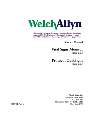
NOTE: See Nurse Call Interface in the Operator’s Manual for complete information on the Nurse Call interface. Vital Signs Monitor
1 6 2 7 3 8 4 9 5
RS-232 Cable
1 6 2 7 3 8 4 9 5
TX Data RX Data DTR Ground
RS-232 DB-9 Nurse Call Contacts: 30Vdc @ 1 amp or 240Vac @ 1 amp
Nurse Call Contact Wires
Common Normally Open
Figure 1-1. Nurse call interface diagram.
The Welch Allyn Vital Signs Monitor provides a switch closure output between two pins of the serial connector (pins 7 and 8). The output is universal in that it is compatible with a wide variety of different systems with no polarity dependence. The Nurse Call output is ohmically isolated from all circuitry. The output is rated for 1 Amp at 240VAC or 30Vdc. During an alarm condition the output is closed, otherwise the output is open. During a power off or power failure condition the output is open.
Specifications The performance specifications of the Vital Signs Monitor are as follows: Patient Population The Welch Allyn Vital Signs Monitor is designed for use with adult and pediatric patients. Welch Allyn defines a pediatric patient as 29 days old and above. THE VITAL SIGNS MONITOR IS NOT INTENDED FOR USE WITH NEONATES. Welch Allyn defines neonates as children 28 days or less of age born at term (37 weeks gestation or more): otherwise, up to 44 gestational weeks. Cuff Pressure Range 0 mmHg - 300 mmHg Initial Cuff Inflation 120, 140, 160, 180, 200, 240, 280 mmHg depending on pressure preset level. Pressure preset default is 160 mmHg.
10
Welch Allyn Vital Signs Monitor
Monitor Service Manual 95P445E Rev. C
General Information
Section 1
Systolic Range Maximum: 250 mmHg Minimum: 60 mmHg Diastolic Range Maximum: 160 mmHg Minimum: 30 mmHg Blood Pressure Accuracy Blood pressure accuracy meets or exceeds SP10-1992 AAMI standards for non-invasive blood pressure accuracy (AAMI standard: ±5 mmHg mean error; 8 mmHg standard deviation). Blood pressure accuracy is validated for pressure measurement using the upper arm only, with the patient in a seated position. Blood pressure is validated against manual auscultatory readings for adults and children above the age of 3. For children under age 3 blood pressures is validated against intraarterial readings. The monitor is not validated for use with neonates. Blood Pressure Determination Time 20 seconds to 45 seconds typical, 165 seconds maximum. Pulse Rate Range (Using SpO2 determination) Maximum: 200bpm Minimum: 40bpm Pulse Rate Accuracy SpO2 Module Heart Rate (Nellcor Puritan Bennett)±3 bpm Blood Pressure Algorithm Heart Rate ±5.0% Overpressure Cutoff 295 mmHg to 330 mmHg Temperature Ranges Maximum – 108 °F (42.2 °C) Minimum – 84.0 °F (28.9 °C) Temperature Accuracy Calibration Accuracy: ±0.2 °F (±0.1 °C) Temperature Determination Time (Oral) 4 seconds typical, 15 seconds maximum (Axillary) 10 seconds typical (Rectal) 15 seconds typical Oxygen Saturation Range (SpO2%) 40-99% oxygen saturation
Service Manual 95P445E Rev. C
Welch Allyn Vital Signs Monitor 11
Section 1
General Information
SpO2 Accuracy Nellcor MP205 ±3% in the range of 70-100% oxygen saturation (1 Standard Deviation) <70% unspecified by the OEM. Nellcor MP506 Without Motion - Adults: 70 to 100% ± 2 digits* With Motion - Adults: 70 to 100% ± 3 digits** Low Perfusion: 70 to 100% ± 2 digits*** <70% unspecified by the OEM Bio compatibility testing has been conducted on Nellcor sensors in compliance with ISO10993-1, Biological Evaluation of Medical Devices, Part 1: Evaluation and Testing. The sensors have passed the recommended bio compatibility testing and are therefore in compliance with ISO 10993-1. * Adult specifications are shown for OxiMax MAX-A sensors. Saturation accuracy will vary by sensor type. Refer to the following Sensor Accuracy Grid. **Applicability: OxiMax MAX-A, MAX-P, and MAX-I sensors. *** Specification applies to monitor performance and was validated with Biotek and Nellcor simulators. Battery Charging (90%-100% capacity in 12 hours). Unit will operate and charge battery simultaneously when connected to power source.
Mechanical Specifications Dimensions Height 6.5 inches (16.5 cm) Length 8.6 inches (21.8 cm) Depth 5.0 inches (12.7 cm) Weight Approximately 6 pounds (2.8 Kg) Mounting Self-supporting on rubber feet Custom Mobile Stand Custom Made Wall Mount Custom IV pole mount Attaches to bed rail
12
Welch Allyn Vital Signs Monitor
Monitor Service Manual 95P445E Rev. C
General Information
Section 1
Electrical Specifications Power Requirements Patient-Rated isolation transformer is connected to AC mains: North American Version: 120 Vac, 60 Hz 0.20 A Input Source, 8 Vdc, 0.75 A Output Source International Version: 220-240 Vdc, 50-60 Hz 0.20A Input Source, 8 Vdc, 0.75 A Output Source Battery (Lead acid, with external charger) A fully charged battery will support 200"typical" blood pressure determinations taken at 7 minute intervals. Battery is 90%-100% charged after 6-12 hours of charging. The battery automatically charges when the Vital Signs monitor is powered through the AC power transformer. The battery will charge faster when the instrument is not in operation.
Environmental Specifications Operating Temperature +10 °C to +40 °C (Except temperature 16 °C to 40 °C) +50 °F to +104 °F Storage Temperature -20 °C to +50 °C -4 °F to +122 °F Relative Humidity 15% to 90% (non-condensing) Operating Altitude -170 m to +4877 m -557 ft to +16,000 ft
Service Manual 95P445E Rev. C
Welch Allyn Vital Signs Monitor 13
Section 1
General Information
Identification Label and Serial Numbering System Defined The identification label for the 52000 Series Vital Signs Monitor is shown below. It is located on the bottom of the unit.
4341 State Street Road Skaneateles Falls, NY 13153
Figure 1-2. Serial number label.
The serial number for the device would consist of nine (9) numbers and a bar code. These would be located in the square below the words "52000 SERIES”. An example of the number and the explanation is shown below: 200200001 The four digits on the left are the year of manufacture of the device. The five digits on the right are the sequence of build starting with 00001 annually. (The example number above would be the first unit built in 2002)
Firmware Identification To confirm the software levels of the Vital Signs Monitor, place the unit into the Configuration Test mode by holding down the “Start” button while the unit is being powered up. The main software versions will appear as follows: • The main unit software will appear in the Systolic and Diastolic windows. • The SpO2 option and temperature option (if installed) will appear in the SpO2 and Temperature displays. Note: Verify the firmware levels listed in Appendix D.
14
Welch Allyn Vital Signs Monitor
Monitor Service Manual 95P445E Rev. C
Service
Section 2
Tools required for Service Table 2-1. Tools required for calibration and repair of the Vital Signs Monitor
DESCRIPTION 100 cc Test Volume
TOOL # T112819
Manufacture Welch Allyn (6 week lead time)
250 cc Test Volume 500 cc Test Volume Bulb and valve Pneumatic tubing (3 ea.) Test Cable (IR) Test Cable (Service Cable Kit) Repair software
T112818 T112854 5088-01 5089-12 66P824 130S60 130S57E
Welch Allyn (6 week lead time) Welch Allyn (6 week lead time) Welch Allyn Welch Allyn Welch Allyn Welch Allyn Welch Allyn
Welch Allyn 9600 Calibrator Welch Allyn calibration key Spot Service Manual Pneumatic clamps (3) Pliers Wire cutter Tweezers Torque bit (T8) Phillips screw driver T10 torx bit 3/8 hex socket Cable tie tool Setra pressure meter (0-10 PSIG) Netech pressure meter Nellcor patient simulator Nellcor patient simulator Nellcor test cable Digital timer "Y" fitting "T" fitting (3)
01800-210 06137-000 4200-145E 21730-001
Welch Allyn Welch Allyn Welch Allyn VWR Scientific 800-932-5000 Tool/Supply Store Tool/Supply Store Tool/Supply Store Tool/Supply Store Tool/Supply Store Tool/Supply Store Tool/Supply Store Tool/Supply Store 2270-01 Setra 800-257-3872 200-2000IN Netech 800-547-6557 SRC-2 for MP205 Nellcor 800-635-5267 SRC-MAX for MP506 Nellcor 8-Dec Nellcor 8456T12 McMaster Car 404-346-7000 9586TPK4 Festo 704-527-1427 9585TPK4 Festo
IBM compatible 486 133 MHz computer or better. The computer must have Windows 95 with a serial port. CPU must have 8 Megabytes of RAM. 2 Digital Multi-Meters. These meters must have 4 1/2 digit displays for accuracy. Power Supply. 0-20 Vdc adjustable with 0-3A output. Service Manual 95P445E Rev. C
Welch Allyn Vital Signs Monitor 15