Ziehm
Exposcop CB7-digital Model CB 745 User Manual
User Manual
46 Pages
Preview
Page 1
TABLE OF CONTENTS
1.0
Introduction 1.1 1.2
2.0
Technical Data 2.1 2.2 2.3 2.4 2.5 2.6 2.7 2.8 2.9
3.0
Shipping Container Unpacking Mounting System Interconnection
System Checkout 5.1 5.2 5.3 5.4
6.0
General Radiation Warning Mechanical-Electrical Warning Electrical Groundinglnstructions Installation and Environment
Installation 4.1 4.2 4.3 4.4
5.0
Power Supply Requirements GeneratorRating Fluoroscopy Operation Radiography Operation X-ray Tube Image Intensifier Monitors Mechanical Dimensions Weight
Safety Precautions 3.1 3.2 3.3 3.4 3.5
4.0
General Special Features
AC Power Check Leakage Current Check Mechanical Movement Operation
Maintenance 6.1 6.2 6.3
User Maintenance DHEW Maintenance Preventive Maintenance
-
Page 6 Page 6
-
-
Page 7
-
-
-
Page Page Page Page Page Page Page Page Page
-
Page 9
-
7 7 7 7 7 7 7 8 8
-
Page 9 Page 9 Page 9 Page 10 Page 10
-
Page 10
-
-
Page 10 Page 10 Page 11 Page 11
-
Page 11
-
-
Page 11 Page 12 Page 12 Page 12
-
Page 13
-
-
Page 13 Page 14 Page 14
-
-
-
-
-
-
-
-
-
-
3
7.0
Mechanical Operation 7.1 7.2 7.3 7.4 7.5 7.6
Page 15
-
Orbital Rotation Swivel Horizontal Vertical
-
Page 16 Page 16 Page 16 Page 16 Page 16 Page 16
-
Page 18
-
Brake/Steering
-
-
***FLUOROSCOPY***
8.0
Introduction 8.1 8.2 8.3
9.0
3 mA Fluoro 6 mA Fluoro Snapshot (8 mA Fluoro) Pulsed Fluoro
kV Adjustment Magnification Image Reversal Image Rotation Iris CoHimator Siot Collimator Image Transfer Image Storage (Disk)
Control Panel Displays! Audible Alarm 11.1 11.2 11.3 11.4 11.5 11.6 11.7 11.8
4
-
kV Display mA Display Elapsed Exposure Time Display X-ray Indicator Standby/Fault Indicator Five Minutes Exposure Indicator Warm Up Time Audible Alarm
Page 18 Page 19 Page 21
Page 22 -
Page 22 Page 22 Page 22 Page 22
Page 23
Manual Controls 10.1 10.2 10.3 10.4 10.5 10.6 10.7 10.8
11.0
-
Operating Modes 9.1 9.2 9.3 9.4
10.0
Basic Operation Mobile Stand Control Panel Monitor Cart Control Panel
-
Page 23 Page 23 Page 23 Page 23 Page 24 Page 24 Page 24 Page 24
-
Page 25
-
-
Page 25 Page 25 Page 25 Page 25 Page 26 Page 26 Page 26 Page 26
-
-
-
-
-
-
-
-
12.0
Picture Storage 12.1 12.2 12.3 12.4 12.5
13.0
-
Clearing Memory Four Image Mode Image Transfer to Disc Image Shifting Image Recall
Hard Copy 13.1 13.2
Videoprinter (optional) CRT Hard Copy Camera
Page 27
-
-
Page 27 Page 27 Page 27 Page 27 Page 27
-
-
Page 28
-
-
-
Page 28 Page 28
-
Page 29
-
-
-
***RADIQGRAPHY***
14.0
Generallnformation 14.1 14.2 14.3 14.4
Dose Rate Time Setting Film Cassette Holder Collimator Size
-
Page 29 Page 29 Page 29 Page 30
-
-
***APPENDIX***
1) 2) 3) 4) 5) 6)
Measuring Data for Radiation Protection Certificate for Standard Measuring Data Registration Number X-ray Tube Performance Protective Tube Housing Test Location of WARNING and CAUTION labels
5
1.0
INTRODUCTION
1.1
General The Ziehm EXPOSCOP CB7-Digital is a mobile X-ray System developed for surgical and diagnostic applications. This C-Arm may be used to perform Fluoroscopy or Spot-Film Radiography. lt is not for use in the presence of flammable anesthetics or other explosive gases. This manual should be thoroughly read and understood before any attempt is made to install, operate or service this equipment. Close attention should be paid to the safety precautions contained in section 3.
1.2
SPECIAL FEATURES The C87-D has been engineered to provide superior quality and performance. Some of the outstanding features include: *
High frequency generator which produces a precise spectrum of radiation capable of superior penetration. The CB7-D can produce a quality image at lower kV levels while dramatically reducing the skin dose.
*
Efficient design of the generator allows the CB7-D to perform fluoroscopy at maximum kV and 3 mA continuously for up to 30 minutes. After this time, the System continues to function at a reduced dose (0.5 mA).
*
Pulsed Fluoroscopy may be selected to reduce the dose by one-haif during extended procedures. -
6
*
Integral digital memory features last image hold.
*
Frame Integration may be selected as an effective noise filtration technique.
*
Magnification achieved with electronic focus within the Image Intensifier for grea-ter resolution.
*
Compact design of the Image Intensifier makes the CB7-D easier to position and maneuver.
*
Unique cable arrangement contributes to the clean design and attractive appearance of the C37-D. lt may also be kept sterile more easily.
*
Fluoroscopy may commence approx. 90 seconds after power is turned on.
2.0
TECHNICAL SPECIFICATIONS
2.1
Power Supply Requirements Line Voltage Single Phase:
110V ÷1- 10% 60 Hz 20 A slow fuse 220/240V +1- 10% 50 Hz 15 A slow fuse -
-
-
2.2
-
GeneratorRating Operating Frequency: 20 kHz kV Range: 36 kV to 110 kV
2.3
Fluoroscopy Operation The kV level ranges from 36 kV to 110 kV and may be adjusted automatically or set manually. The mA level is adjusted automatically and may range up to 3.0 mA, 6.0 mA or 8 mA (snapshot mode) as selected by the Operator.
2.4
Radiography Operation The kV level ranges from 36 kV to 110 kV and is preset during the preceding fluoroscopy or may be set manually. The mA level is a constant 20 mA. The duration of radiography is set manually from 0.1 sec. to 4.0 sec.
2.5
X-ray Tube Stationary Anode with dual focus. Inherent filtration equivalent to at least 3 mm Al. Focal Spot Size Fluoro: 0.6 mm Radiography: 1.5 mm
2.6
Image Intensifier Cesium lodide Fluoroscopic Grid Pb 8/1 40 Standard size 7fl/4~ (17 cm/10 cm) Optional size 9‘76“ (23 cm/15 cm) Electronic magnification factor of 1.5
2.7
Monitors Screen size: Bandwidth: Raster Lines:
17“ 20 Mhz 525 at 60 Hz; 625 at 50 Hz.
7
2.8
Mechanical Dimensions Focal spot to Image Intensifier distance: Cone to Image Intensifier housing: Central beam to C-Arm: C-Arm orbital movement: C-Arm rotation: +1C-Arm swivel: ÷1-
2.9
37“ 25“ 26“ 115 deg. 225 deg. 12 deg.
Weight Mobile Stand: 460 ibs -Monitor Cart: 275 ibs
PICTURE 1
All dimensions in millimeters
8
3.0
SAFETY PRECAUTIONS
3.1
General The user of this manual is directed to carefully read and review the instructions, warnings and cautions contained herein prior to the installation, Operation or service of this equipment. The installation and service of the CB7-D is to be performed by authorized, qualified personnel with the support of Ziehm Technical Services Representatives. Those authorized to operate, participate in or supervise the Operation of the equipment must be thoroughly familiar and compiy completely with the currentiy established safe exposure factors and procedures described in publications, such as: Subchapter J of Title 21 of The Code of Federal Regulations, “Diagnostic X-ray Systems and Their Major Components“, as revised or replaced in the future.
3.2
Radiation Warning This equipment produces X-rays which are dangerous to both Operator and others in the vicinity unless established safe exposure procedures are strictly observed. The useful and scattered beams can produce serious or fatal bodily injuries to any persons in the surrounding area if used improperly. Adequate precautions must always be taken to avoid exposure to the useful beam, as weil as to leakage from within the source housing or to scattered radiation resulting from the passage of radiation through matter. Those responsible for the planning of X-ray equipment installations must be thoroughly familiar with “Structural Shielding Design and Evaluation for Medical Use of X-rays“ as revised or replaced in the future.
3.3
Mechanical Electrical Warning -
All of the moveable assemblies and parts of this equipment should be operated with care and routinely inspected in accordance with the manufacturer‘s recommendations contained in this manual. Only properly trained and authorized personnel should be permitted access to any internal parts. Be sure line disconnect switches are opened and other appropriate precautions are taken before opening access doors, removing enciosure panel, or attaching accessories. Do not remove the covers from the generator untii the power has been turned off. Failure to comply with the foregoing may result in serious injuries to the Operator or those in the vicinity.
9
3.4
Electrical Groundinglnstructions The equipment must be grounded to an earth ground by a separate conductor. The neutral side of the line is not to be considered the earth ground. On equipment provided with a line cord, the equipment must be connected to a properly grounded, three-prong receptacle. Do not use a three-prong to two-prong adapter.
3.5
Installation and Environment Except for installations requiring certification by the manufacturer per Federal Standards, see that a radiation protection survey is made by a qualified expert in accordance with NCRP No. 33, section 6 as revised or replaced in the future. Perform a survey after every change in equipment, workload, or operating conditions which might significantly increase the probability of persons receiving more than the maximum permissible dose equivalent. This equipment is not for use in the presence of flammable anesthetics or other explosive gases. Failure to heed this warning may result in a fire or an explosion.
4.0
INSTALLATION The installation of this equipment should be performed by authorized, qualified personnel who have carefully read and reviewed this manual.
4.1
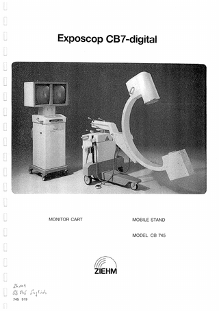
Shipping Container The CB7-D is shipped on a single pallet and contains the mobile stand, monitor cart, an unmounted monitor case assembly and a box containing manuals, cassettes and a cassette holder. The equipment should be carefully inspected and any shipping damage must be reported immediately to the shipping carrier in the form of a damage claim.
4.2
Unpacking Remove the outside of the shipping container and inspect for any shipping damage. Remove the monitors and the box containing the manuals and cassettes. NOTE:
The three short wooden blocks below one end of the pallet may be unbolted and removed to tip the pallet. This will facilitate the removal of the monitor cart and mobile stand.
Remove the metal brackets which hold the monitor cart in place. Release the brakes on the front wheels and carefully place the monitor cart on the floor. Remove the metal brackets holding the mobile stand, release the hand brake (lift the lever located in the center of the control panel) and carefully place the stand on the floor. NOTE:
10
Care must be exercised when removing the metal brackets so that the paint is not scratched or chipped.
4.3
Mounting The monitor set is the only item which requires mounting. The monitors are clearly identified as either left or right (as viewed from the front). Remove the rear panel of the monitors and place the monitor case assembly on the cart‘s mounting surface. Route the wiring into the monitors from the hole in the bottom and secure with four allen screws from below. The power cord and video cable are connected at the rear of the monitor. Two additional wires are then connected, one on the monitor board and one on the yoke rotation board. The wires, and the location they connect to, are individually marked. A two-wire cable is provided for the left monitor and is connected to the cable which services the amber light 011 top. Attach the ground wires to the rear panel and cart. Secure the rear panel and access plate.
4.4
System Interconnection The monitor cart and mobile stand are connected with a single heavy-duty cable which attaches at the rear of the monitor cart. lt should be connected before the System is powered on. The line cord on the monitor cart should be plugged into a properly grounded and rated outlet.
5.0
SYSTEM CHECK-OUT Service personnel are cautioned to observe all CAUTIONS and WARNINGSas they appear in the text of this section, and observe the general safety precautions outlined in the Service Engineer‘s Safety Manual, U95:M. The instructions for system check-out require that the operator has read this entire manual and is familiar with the Operation of this equipment.
5.1
AC Power Check lnspect the AC power cord on the system to ensure that it is compatible with the AC power receptacle. Verify that the AC line voltage is proper for the Operation of the equipment. WARNING:
The unit must be grounded through the U-Shaped grounding prong of the line plug. Do not use a 3-prong to 2-prong adapter unless properly installed by a licensed electrician. Failure to comply with the foregoing may cause serious or fatal injuries to the Operator and other persons in the surrounding area.
NOTE:
System input power must be set to match service LINE voltage. For voltages above and below 110 V AC input LINE voltages must be compensated for by adjusting to either 100 V AC, or 120 V AC at the terminal block located at the lower rear of the monitor cart.
11
5.2
Leakage Current Check The installation of this X-ray equipment may include a check of the leakage current. This should be performed with a properly calibrated leakage meter, in aceordance with the leakage meter instructions. Inspect the ground leads for solid ground connections. Insert a properly calibrated leakage meter (with 100 0 input impedance) in series with the CB7-D line cord per the leakage meter instructions. Turn on power and verify that the leakage current does not exceed 100 1iA in either normal or reversed line polarity.
-
5.3
Disconnect the leakage meter and insert the CB7-D line cord into the AC receptacle. Connect the black lead of the leakage meter to an exposed metal surface of the CB7-D per the leakage meter instructions. Turn on power and verify that the leakage current is no more than 10 ~tA. Mechanical Movement The C-Arm is capable of moving in an arc (115 deg.), rotating in the vertical plane (+1- 225 deg.) or swiveling ( +1- 12 deg.). One at a time, release each brake and verify full and unrestricted movement. Secure each brake when finished. Release the horizontal brake and verify the approximate 20 cm of horizontal travel. Release the hand brake on the mobile cart by pulling the handle up and check that the cart moves freely and may be steered by turning the brake handle. Turn on system power at the monitor cart control panel, and verify that the vertical position motor can raise and lower the C-Arm when operated from the mobile cart control panel.
5.4
Operation X-ray equipment operators should protect themselves and others in the area with such devices as lead aprons or shields. All standard safety precautions must be observed and exposure to the X-ray beam must be strictly avoided. The collimator may be used toxestrict the radiation beam during checkout. After the system has been properly connected and powered on, the CB7-D will be in the following operating mode: * * * *
Fluoroscopy, 3 mA max. Automatic dose rate control Live image on left monitor with last image hold Normal picture size (no magnification)
After power on, the kV level is set at 36 kV as indicated by the kV display. Fluoroscopy may commence once the cathode filament has preheated (ninety seconds after power up) and is activated by pressing the hand or foot switch. In the automatic dose control mode, the kV will be adjusted automatically and the resulting setting will be displayed. After fluoro, the display will show the last kV setting. The mA display operates only when fluoroscopy is performed and only in the 3 mA or 6 mA modes.
12
Check that the siot and iris collimators may be opened and closed and the siot collimator can rotate. Check that the image reversal and magnification (zoom) functions operate properly and that the “kV manual“ mode may be selected and the kV setting may be adjusted manually. NOTE:
Do not perform Fluoroscopy or Radiography in the kV manual mode at a kV level higher than the object requires. This will prevent the camera from being overdriven by high light levels. Verify that the Radiography mode may be initiated with the hand switch only and that the time setting for radiography is adjustable from 0.1 sec. to 4.0 sec.
On the monitor cart, verify that the live fluoroscopy image appears on the left monitor and the last image is held after a fluoro is completed. When exposure occurs (active radiation from the generator) during either fluoroscopy or radiography, the amber light on top of the left monitor should be illuminated and the two rectangles on the top of the monitor display should disappear. Verify that the monitor image may be rotated from the controls on the mobile cart. Check that the cassette light on the monitor cart is illuminated when the film cassette is fully inserted. 6.0
MAINTENANCE
6.1
User Maintenance The inspection procedure listed in table 1 should be performed by the user of this equi pment.
TABLE 1
INSPECTION REQUIREMENTS
INTERVAL
1) Radiation Leakage
1 month
2) Deadman Switches
1 month
3) Exposure Indicator
1 month
4) Audible Exposure Indicator
1 month
INSTRUCTIONS
Inspect for physical damage which could affect radiation shielding. Confirm that each of the exposure switches work properly. They should require continuous pressure to maintain the exposure and release of the switch terminates the exposure. Confirm that the mA and kV meters and the exposure lamp on top of the left monitor functions continuously only during an exposure. Confirm that the audible exposure indicator operates during radio graphy and after 5 minutes of exposure. 13
5) Warning and Caution Labels
1 month
6) Radiation Leakage
1 month
7) Line Cord
1 month
8) Mechanical Cone
1 month
6.2
Inspect and confirm that all WARNING and CAUTION labels have not been defaced or worn so as to be illegible. Look for physical damage to the X-ray tube assembly which could affect radiation shielding proper limitation of the X-ray beam. Inspect and confirm that the line cord and plug are not broken or otherwise damaged. Inspect and confirm that the mechanical cone is properly installed and secured installed for a SSD of 30 cm. Verify that the warning label is not defaced.
DHEW MAINTENANCE Maintenance procedures, necessary to insure (continued) compliance with DHEW (Dep. of Health and Welifare) requirements are contained in the recommended Schedule of Maintenance supplied with your equipment. This maintenance should be performed by authorized and qualified service personnel at the prescribed interval, according to the instructions given in the appropriate manual. As noted in (FDA) 75-8005, a Practitioners Guide to the Diagnostic X-ray Equipment Standard: “lt is up to the practitioner to have his X-ray maintained according to the schedule furnished by the manufacturer to insure compliance with the standard for the life of the equipment. Failure to follow the manufacturer‘s maintenance instructions could relieve the manufacturer of responsibility for continued compliance.“
6.3
Preventive Maintenance The following preventive maintenance should be performed at six month intervals, or whenever the equipment has been subjected to any use or conditions which may cornpromise the safe Operation of the System. This maintenance is to be arranged by the user and must be performed by qualified personnel. 6.3.1
kV Adjustment
6.3.2
mA Adjustment
6.3.4
Electrical Functions * * * * * * * * *
14
Automatic dose rate control Display of mA during 3 mA and 6 mA fluoro Radiography time control functions properly Fluoroscopy terminates after release of button Collimator controls functional Monitor controls functional Displays function properly Line cord in good condition and properly grounded Cables in good condition
7.0 MECHANICAL OPERATION PICTURE 2
TABLE 2 1 2 3 4 5 6 7 8 9 10 11 12 13 14 15 16 17 18 19 20 21
X-ray TV Camera Image Intensifier Removable cassette holder for Spot Film Radiography Brake for horizontal travel A (20 cm) Brake for swivelling in horizontal plane B Brake for rotation of C-Arm in vertical plane C Motor-driven vertical movement D Brake lever/steering handle for mobile stand wheels Handswitch for Fluoroscopy and Radiography Brake for orbital movement of C-Arm in plane E Footswitch holder P0 attachment Footswitch for Fluroroscopy High Frequency X-ray Generator TV Monitors Monitor Cart Control Panel Cassette drawer for Format Camera Location of Format Camera P0 attachment P0 Cable holder X-ray indicator
:~IIIIIIItlIIIIIItIIIIII~I
III~I
liii 11111
1 III~_~
wnimmm
-
1111W 1111111
15
The mechanical brakes for the C-Arm should always be secured in the locked position. This is especially important when the equipment is in transport. The locked position of the handles may be adjusted by lifting the spring-loaded handle, rotating it to a new position and dropping it back down.
7.1
Orbital The CB7-D is capable of 115 degrees of orbital movement. The brake listed as item 10 in pic. 2 is used to lock the C-Arm into the desired orbital position.
7.2
Rotation The ÷1- 225 degrees of rotation which the C-Arm is capable of is secured by brake item 6 in pic. 2. Care must be taken not to overextend the rotation capability of the System or the C-Arm cable may be strained.
7.3
Swivel Brake item 5 in pic. 2 secures the +1- 12 degrees of C-Arm swivel.
7.4
Horizontal The C-Arm i~ capable of approximately 20 cm of horizontal travel which is secured by brake item 4 pic. 2.
7.5
Vertical The 43 cm of vertical travel is accomplished under motor control and may be operated from the mobile stand control panel (up-down arrows). This travel is illustrated by dimension D in item 7 pic. 2.
7.6
Brake/Steering The brake lever, item 8 in pic. 2, located in the center of the mobile stand control panel, is used for both steering and braking. When it is pushed down, the brakes are engaged. When it i~ lifted up, the brakes are released. The mobile stand may be maneuvered by grasping the handles on either side as illustrated in pic. 3a. The two wheels located beneath the lever may also be steered as illustrated in pic. 3b and 3c.
16
PICTURE 3
Q
b
c
/
/
/
/
/ /
/
17
***FLUORQSCOPY***
8.0
INTRODUCTION The use of the Ziehm CB7-D in Fluoroscopy can be as simple as powering on the system, waiting approx. 90 seconds for the cathode filament to preheat, and activating the hand or foot switch to view the first image. lt is also sophisticated enough to allow these options: * * * * * * * * * * * *
6 mA Fluoro 8 mA Snapshot Pulsed Fluoroscopy Manual Control of kV Zoom (Magnification) Disable Filtering Multi-Format Storage Dual Monitor Display Image Reversal Image Rotation Iris Collimation Siot Collimation with Rotation
These options are described in subsequent sections of this manual. This document should be carefully read before any attempt is made to operate the CB7-D. This will contribute to the safe use of the equipment and allow the Operation to be quickly mastered.
8.1
Basic Operation Before the system is powered up, the cable connecting the mobile stand and the monitor cart must be installed, and the line cord should be connected to a properly grounded outlet of adequate capacity. The CB7-D is switched on from the mobile cart control panel. After power up, the System is in-the following operating modes: * * * * * *
Fluoroscopy, 3 mA max. Filter enabled (Frame integration) kV Automatic (Automatic Dose Rate Control) Normal picture size Live Image on left monitor Last Image Hold
Approx. 90 seconds after power up (during which time the cathode filament preheats) fluoroscopy can be initiated by activating the hand or foot switch. The brightness and contraSt controls on the monitor may then be adjusted. After the switch is released, the last image will be held cm the left monitor.
18
PIC. 4 illustrates the differences among continuous, pulsed, and snapshot fluoroscopy. When radiation is present, the live image is displayed. When radiation is not present, the last live image will be held and will continue to be displayed until the frame counter is changed, or a new live image displayed.
PICTURE 4
RADIATION PRESENT LAST IMAGE STORED AND DISPLAYED
FLUOROSCOPY INITIATED BY OPERATOR CONTINUOUS FLUOROSCOPY PULSED MODE
1
.
SNAPSHOT MODE TIME---->
8.2
Mobile Stand Control Panel A diagram of the mobile stand control panel is shown in pic. 5, with the control buttons and display locations numbered individually. Table 5 includes a numerical listing of the buttons and display locations, and indicates the section within this manual which describes the use of each.
19
MOBILE STAND
-
CONTROL PANEL PIC. 5
cD ~ ~ 1
~0 00 ~ ( ‚~
[ist ~]
___
~ ~
23 20
24
~
25
27
~~2i
TABLE 5 1 2 3 4 5 6 7 8 9 10 11 12 13 14 15 16 17 18 19 20 21 22 23 24 25 26 27 28 29 30
20
(Sec. 7.5) (Sec. 11.6) (Sec. 11.1) (Sec. 11.1) (Sec. 11.2) (Sec. 11.3) (Sec. 11.4) (Sec. 11.5) (Sec. 11.7) (Sec. 14.3) (Sec. 14.0) (Sec. 14.2) (Sec. 9.1) (Sec. 9.4) (Sec. 9.3) (Sec. 10.1) (Sec. 10.1) (Sec. 10.7) (Sec. 10.7) (Sec. 10.6) (Sec. 10.4) (Sec. 10.3) (Sec. 10.5) (Sec. 10.5) (Sec. 10.8) (Sec. 9.2) (Sec. 10.9) (Sec. 8.0) (Sec. 8.0)
Vertical Position Motor Controls Emergency Switch 0ff Clear Radiation Time/Clear Audio Alarm Radiography Time Display kVDisplay mA Display Fluoroscopy Time Display X-ray Indication Stand by/Failure/Overheating/Indication Warm Up Time Indication Radiography Field Size Radiography Mode Adjust Radiography Time Display .Yluoroscopy Mode Pulsed Fluoroscopy Snapshot Fluoroscopy kV Manual kV Manual Adjustment Siot Collimator, Open/Ciose Rotation of Siot Collimator Iris Collimator, Open/Ciose Image Reversal Magnification (Zoom) Image Rotation, Left Monitor Image Rotation, Right Monitor Image Transfer, Left/Right Monitor 6 mA max. Image Storage (Disk) Hand Switch (Fluoroscopy and Radiography) Footswitch (Fluoroscopy)
28~ 28
~
8.3
Monitor Cart Control Panel PICTURE 6
43
33 34~c~
~6
38
4‘
(~2~‘j~ 39
TABLE 6 31 32 33 34 35 36 37 38 39 40 41 42 43
(Sec. 12.0) (Sec. 12.2) (Sec. 12.3) (Sec. 12.4) (Sec. 12.5) (Sec. 13.1) (Sec. 13.2) (Sec. 13.2)
Contrast Control with pull switch Main position = normal contrast Pulled = manual adjustment Brightness Control with pull switch Main position = VCR synchronized Pulled = normal brightness Clear Image Storage 4 Images Mode Image Storage (Disk), parallel to button 28 Image Transfer, Left/Right Monitor, parallel to button 26 Frame Counter, Up/Down Screening Hard Copy Videoprinter Exposure Hard Copy CRT Exposure Hard Copy CRT Field Indication Power 0ff Power On X-ray Indication, parallel to 8 -
-
21
9.0
OPERATING MODES The filament current is always controlled by the System in response to the kV level at which the tube is operating. The range, or maximum mA value, is selectable by the Operator.
9.1
3 mA Fluoro
14
The 3 mA mode (range of 0.2 mA to a maximum of 3 mA filament current) is the standard fluoroscopic operating mode which the System enters after power on. The system is in the 3 mA mode when button 14 (Fluoroscopy) is selected and the control light is on.
9.2
6 mA Fluoro
27
The 6 mA mode (range of 0.2 mA to 6.0 mA) is used when working with dense objects such as the pelvic region. lt is selected by pressing button 27 on the mobile stand and the control light turns on. lt also selects the storage image integration filter to reduce the image noise. Pressing it once more will return the CB7-D to the 3mA mode.
9.3
Snapshot (8 mA)
16
The snapshot mode is selected by pressing button 16 on the mobile stand. Depressing the-hand switch will initiate the snapshot. Maximum integration is used to create the final image. Pressing button 16 once again, the control light turns off. The System returns to the 3 mA mode.
9.4
Pulsed Fluoro
15
JL~L Pulsed fluoroscopy may be selected by pressing button 15 so it is illuminated. When the hand or foot switch is pressed the X-ray beam is turned on and off at one second intervals to reduce the dose while progression of the procedure may be viewed. 3 mA is selected. Pressing button 15 again will return the system to continuous fluoroscopy.
22