1 Page
Preview
Page 1
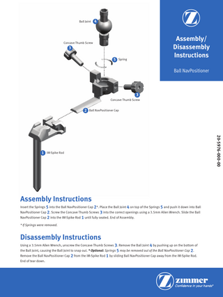
Ball Joint
4
Assembly/ Disassembly Instructions
Concave Thumb Screw
3 5 Spring
Ball NavPositioner
3 Concave Thumb Screw
2 Ball NavPositioner Cap
Assembly Instructions Insert the Springs 5 into the Ball NavPositioner Cap 2*. Place the Ball Joint 4 on top of the Springs 5 and push it down into Ball NavPositioner Cap 2. Screw the Concave Thumb Screws 3 into the correct openings using a 3.5mm Allen Wrench. Slide the Ball
NavPositioner Cap 2 into the IM-Spike Rod 1 until fully seated. End of Assembly. * If Springs were removed.
Disassembly Instructions Using a 3.5mm Allen Wrench, unscrew the Concave Thumb Screws 3. Remove the Ball Joint 4 by pushing up on the bottom of
the Ball Joint, causing the Ball Joint to snap out. * Optional: Springs 5 may be removed out of the Ball NavPositioner Cap 2.
Remove the Ball NavPositioner Cap 2 from the IM-Spike Rod 1 by sliding Ball NavPositioner Cap away from the IM-Spike Rod. End of tear down.
20-5976-000-00
1 IM-Spike Rod