User Manual
135 Pages
Preview
Page 1
333
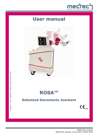
User manual
Photo courtesy of B-to-B Design in Montpellier, France - © Medtech
ROSA™ Robotized Stereotactic Assistant
ROSA User manual ROSA-041 Version 2.5.8-C-EN 13-NOV-2014
Table of contents
1. INTRODUCTION _________________________________ 1 1.1 USER MANUAL CONTENTS _______________________________________________________________ 1 1.2 CONTRAINDICATIONS __________________________________________________________________ 1 1.3 GENERAL WARNINGS AND PRECAUTIONS _____________________________________________________ 1 TRAINING, USE AND MAINTENANCE _____________________________________________________________ 1 ELECTRICAL HAZARDS _______________________________________________________________________ 2 RISKS RELATED TO RADIATION _________________________________________________________________ 3 RISKS RELATED TO TRANSPORT AND IMMOBILIZATION OF THE SYSTEM AND THE PATIENT _________________________ 4 MECHANICAL HAZARDS _____________________________________________________________________ 5 RISK OF CONTAMINATION ____________________________________________________________________ 6 USE OF THE SOFTWARE ______________________________________________________________________ 6 1.4 SYMBOLS ON THE LABEL_________________________________________________________________ 8 1.5 OTHER SYMBOLS ON THE DEVICE ___________________________________________________________ 9 1.6 PACKING LIST ________________________________________________________________________ 9 1.7 PACKING LIST - OPTIONS _______________________________________________________________ 10 1.8 CONTACT _________________________________________________________________________ 10 1.8.1 HEADQUARTERS____________________________________________________________________ 10 1.8.2 NORTH AMERICAN OFFICES ____________________________________________________________ 10
2. GENERAL PRESENTATION ________________________ 11 2.1 GENERAL DESCRIPTION ________________________________________________________________ 11 2.1.1 OPERATION_______________________________________________________________________ 11 2.1.2 INTENDED USE _____________________________________________________________________ 12 2.1.3 INDICATIONS FOR USE ________________________________________________________________ 13 2.1.4 RESTRICTIONS FOR USE _______________________________________________________________ 13 2.1.5 PERFORMANCES ___________________________________________________________________ 13 2.2 DETAILED DESCRIPTION OF THE MOBILE TROLLEY _______________________________________________ 14 2.2.1 THE ROBOT ARM ___________________________________________________________________ 15 2.2.2 THE TOUCH SCREEN _________________________________________________________________ 15 2.2.3 FIXATION OF THE PATIENT’S HEAD ________________________________________________________ 16 2.2.4 STABILIZATION SYSTEM WITH HYDRAULIC ACTUATORS __________________________________________ 22 2.2.5 VIGILANCE DEVICE __________________________________________________________________ 23 2.3 INSTRUMENTATION___________________________________________________________________ 24 2.3.1 POINTER PROBE ____________________________________________________________________ 26 2.3.2 OPTICAL DISTANCE SENSOR ____________________________________________________________ 26 2.3.3 INSTRUMENT HOLDER ________________________________________________________________ 27 2.3.4 VENTRICULAR ENDOSCOPY INSTRUMENT HOLDER _____________________________________________ 27 2.3.5 TRANSNASAL ENDOSCOPY INSTRUMENT HOLDER ______________________________________________ 28 2.3.6 MICRODRIVE HOLDER ________________________________________________________________ 28 2.3.7 LEKSELL FRAME X-RAY PLATES __________________________________________________________ 28 2.3.8 LEKSELL FRAME REGISTRATION PLATES _____________________________________________________ 29 2.3.9 ROBOT ARM X-RAY PATTERN ___________________________________________________________ 29
ROSA-041-2.5.8–C-EN
2.4 ACCESSORIES _______________________________________________________________________ 29 2.4.1 HEAD-HOLDER _____________________________________________________________________ 30 2.4.2 STEREOTACTIC FRAME ________________________________________________________________ 31 2.5 REGISTRATION METHODS_______________________________________________________________ 32 2.5.1 MANUAL REGISTRATION USING SKIN FIDUCIALS _______________________________________________ 32 2.5.2 REGISTRATION WITH BONE FIDUCIALS _____________________________________________________ 34 2.5.3 SURFACE MATCHING REGISTRATION ______________________________________________________ 36 2.5.4 REGISTRATION WITH THE LEKSELL STEREOTACTIC FRAME _________________________________________ 41 2.6 PLANNING ON SEPARATE PLANNING STATION _________________________________________________ 45 2.6.1 OBJECTIVE _______________________________________________________________________ 45 2.6.2 THE PLANNING SOFTWARE _____________________________________________________________ 45
3. PREPARATION AND SETUP _______________________ 46 3.1 PREPARATION OF INSTRUMENTS AND ACCESSORIES _____________________________________________ 46 3.1.1 CLEANING AND DISINFECTING INSTRUMENTS ________________________________________________ 46 3.1.2 STERILIZING INSTRUMENTS ____________________________________________________________ 46 3.1.3 DRAPES AND ACCESSORIES _____________________________________________________________ 47 3.2 PATIENT IMAGING ___________________________________________________________________ 47 3.2.1 3D IMAGING ACQUISITION PROTOCOL (MRI, CT) _____________________________________________ 47 3.2.2 2D X-RAY IMAGE ACQUISITION PROTOCOL __________________________________________________ 48 3.2.3 DTI IMAGE ACQUISITION PROTOCOL ______________________________________________________ 49 3.2.4 PET-SCAN IMAGE ACQUISITION PROTOCOL __________________________________________________ 49 3.3 SWITCHING THE DEVICE ON _____________________________________________________________ 50 3.4 INSTALLATION AND IMMOBILIZATION OF THE MOBILE TROLLEY _____________________________________ 51 3.5 STERILE DRAPES _____________________________________________________________________ 52 3.6 STOPPING AND CLEANING THE DEVICE ______________________________________________________ 52 3.7 EMERGENCY PROCEDURE _______________________________________________________________ 53 3.7.1 FULL REMOVAL ____________________________________________________________________ 53 3.7.2 PARTIAL REMOVAL __________________________________________________________________ 54
4. THE USER INTERFACE ___________________________ 55 4.1 WELCOME SCREEN ___________________________________________________________________ 55 4.2 PATIENT FOLDER MANAGEMENT SCREEN ____________________________________________________ 55 4.3 SURGERY CHOICE ____________________________________________________________________ 56 4.4 PLANNING INTERFACE _________________________________________________________________ 58 4.4.1 THE UPPER STRIP (IN RED) _____________________________________________________________ 60 4.4.2 PRINCIPAL IMAGE DISPLAY ZONE (IN GREEN) _________________________________________________ 60 4.4.3 THE VIEW FOR DISPLAY SELECTION STRIP (IN BLUE)_____________________________________________ 62 4.4.4 THE TOOLS ZONE (IN VIOLET) ___________________________________________________________ 63 4.4.5 PLANNING TAB ____________________________________________________________________ 65 4.4.6 REGISTRATION TAB __________________________________________________________________ 78 4.4.7 GUIDANCE TAB ____________________________________________________________________ 79 4.5 MANAGING AND ADDING IMAGES_________________________________________________________ 93 4.5.1 SELECTING A REVIEW FROM CD/USB/PACS ________________________________________________ 94 4.5.2 CASE OF DTI-TYPE IMAGES ____________________________________________________________ 94 4.6 REGISTRATION WITH ATLAS: ____________________________________________________________ 95 4.7 POSITIONING AID ____________________________________________________________________ 98 4.7.1 CHOICE OF ORIENTATION OF PATIENT'S HEAD ________________________________________________ 98 ROSA-041-2.5.8–C-EN
4.7.2 POSITIONING OF ROBOT _____________________________________________________________ 100 4.8 SURFACE REGISTRATION VERIFICATION INTERFACES ____________________________________________ 101 4.8.1 INTERFACE FOR ADJUSTING INITIAL POINTS TAKEN WITHIN IMAGE AND ACQUIRED BY ROBOT ________________ 101 4.8.2 INTERFACE FOR DISPLAYING INITIAL POINTS AND CROSS ACQUIRED BY ROBOT __________________________ 103 4.9 NAVIGATION INTERFACE FOR REGISTRATION VERIFICATION _______________________________________ 104 4.9.1 NAVIGATION ZONE _________________________________________________________________ 106 4.10 MANUAL AND SEMI-AUTOMATIC MULTI-MODALITY FUSION INTERFACES ____________________________ 107 4.10.1 OVERALL PRESENTATION OF FUSION ADJUSTMENT INTERFACE ___________________________________ 108 4.11 X-RAY IMAGE REGISTRATION INTERFACE __________________________________________________ 110 4.12 INTERFACE FOR LEKSELL FRAME REGISTRATION WITH 3D IMAGE __________________________________ 112 4.13 CONTRAST MANAGEMENT INTERFACE ____________________________________________________ 113 4.14 ROSA ERROR MESSAGES _____________________________________________________________ 116 4.14.1 PRINCIPAL ROSA™ ERROR MESSAGES ___________________________________________________ 116
5. PRESERVATION OF THE DEVICE AND INSTRUMENTS __ 118 5.1 5.2 5.3 5.4 5.5
ENVIRONMENTAL CONDITIONS __________________________________________________________ 118 CLEANING THE DEVICE ________________________________________________________________ 118 STORING AND PROTECTING THE DEVICE ____________________________________________________ 118 TRANSPORTING THE DEVICE ____________________________________________________________ 118 STORING AND PROTECTING THE INSTRUMENTS _______________________________________________ 119
6. SERVICE AND MAINTENANCE ____________________ 120 7. TROUBLESHOOTING ___________________________ 121 7.1 TROUBLESHOOTING GUIDE _____________________________________________________________ 121 7.2 DATA RECOVERY PROCEDURE IN CASE OF INTERRUPTION ________________________________________ 125
8. TECHNICAL INFORMATION ______________________ 126 8.1 ELECTROMAGNETIC EMISSIONS __________________________________________________________ 126 8.2 ELECTROMAGNETIC IMMUNITY __________________________________________________________ 127 8.3 RECOMMENDED SEPARATION DISTANCES BETWEEN PORTABLE AND MOBILE RF COMMUNICATION EQUIPMENT AND THE ROSA™ DEVICE ________________________________________________________________________ 129 8.4 ROSA™ DIMENSIONS ________________________________________________________________ 130
ROSA-041-2.5.8–C-EN
Introduction 1. Introduction 1.1
User manual contents
This User manual is considered as the reference document for users of the ROSA system. It is not a technical maintenance or service manual. For technical instructions about the device, please contact Medtech’s Customer Service or one of its approved representatives. A troubleshooting guide is provided in §7. The ROSA device must only be used after reading the instruction manual and after having received the appropriate training. Please contact Medtech’s Customer Service if unsure how to use the device.
1.2
Contraindications
The device does not contain any specific contraindications. The contraindications to the use of the ROSA device include any medical problems likely to constitute a contraindication to the medical procedure itself.
1.3
General warnings and precautions
The proper use of this equipment assumes that the operating personnel is perfectly familiar with the user manual. This manual must be examined in detail before implementing the system. Special attention must be paid to safety instructions relating to the people and the system. WARNING This symbol is present when a warning alerts you to a potential danger to health or life. CAUTION This symbol is present to prevent a risk of deterioration of the equipment in case of a handling error. REMARK This symbol is present to provide a general observation or information relating to procedures, events or practices which are recommended or essential for a successful operation.
Training, use and maintenance ROSA-041-2.5.8–C-EN Page 1
Introduction The ROSA device is a neurosurgery assistance tool. It must only be used by authorized surgeons trained in the use of the device by Medtech or by personnel authorized by Medtech. It is not a replacement for the knowhow and experience of the surgeon. The ROSA device must only be used for its intended use (see the list of indications). The ROSA device must only be used after reading the instruction manual and after having received the appropriate training. Please contact Medtech’s Customer Service if unsure how to use the device. Do not open the device. In case of any issue or breakdown, do not intervene: maintenance and service operations must only be carried out by Medtech’s Customer Service or any of its approved representatives. When used in compliance with the indications for maintenance, the device can be run in permanent operation.
All wastes and residues must follow the hospital recycling guidelines.
Electrical hazards In order to avoid any risk of electric shock, the ROSA device must only be connected to an electric power network equipped with protective earth. Device is class I, type BF. IPx0 protection: Device without special protection against the penetration of liquids. Do not pour any liquids over the device. If at startup, the screen remains black : - Check that the touch screen is powered (button on the right side of the screen) and/or - Restart the PC by pressing the black push button located next to the DVD drive on the rear panel of the device. If at startup the touch screen slab does not work, turn off the monitor by pressing the button located on the right side of the screen for 5 seconds. Wait for 5 seconds and then turn the monitor back on. Wait 1 minute after the extinction of the touch screen before turning the power switch of the device to "0". Windows operating system has not yet
ROSA-041-2.5.8–C-EN Page 2
Introduction completed its shutdown procedure.
To restart the device, wait for at least 1 minute after shutting down.
Risks related to radiation Risks generated by laser beam exposure: The ROSA device uses laser technology for the automatic registration. This laser is of class 2 (power inferior to 1 mW, eye protection by the palpebral reflex). Do not orient the laser beam neither to the eyes nor to any light reflecting surfaces such as mirrors, in order to avoid any direct or indirect exposure to laser beam. Do not orient the laser towards the patient’s eyes, the user’s eyes or a third’s eyes.
The device requires specific precautions regarding the EMC. It must be set up and initiated according to the EMC information provided in §8.
Portable and mobile radio frequency communication devices might affect the operation of the device.
Usage of accessories, transducers and cables other than those specified in §8, with the exception of the transducers and cables sold by Medtech (as spare parts of internal components) might cause increased emissions or decrease immunity of the device. The device must not be used adjacent to or stacked on top of any other equipment. If necessary, verify its correct operation in the corresponding configuration.
ROSA-041-2.5.8–C-EN Page 3
Introduction Risks related to transport and immobilization of the system and the patient Risks due to improper attachment of the patient’s head: check for sufficient stability of the device once the immobilization system is put in place. Residual risks due to improper attachment of the patient’s head: check that the skull is correctly secured in the head holder or frame and that the device is correctly attached to the head holder or frame before beginning the procedure. Risks due to improper attachment of the patient’s head: the device must be used with a head holder or a frame ensuring proper immobilization of the patient's head. This immobilization system must be approved and installed by a trained professional. Residual risks due to improper attachment of the patient’s head: check that the attachment of the articulated arm or support arm to the head holder or frame is correctly tightened. It is not recommended to use the articulated attachment arm for surgery where the patient can be awake. Verify the fixation of the device to the table before beginning the registration. The operating table should not be moved once the patient's head is secured to the ROSATM device. The actuators of the device stabilization feet should not be activated once the patient’s head is secured to the ROSA device. Before loading the data from a registration completed before a failure, ensure that the patient’s head has not been moved in the meantime Pinch hazard: do not place fingers or feet under the mobile part of the stabilization feet before immobilization of the system. Verify the position of the device and its environment when using the remote control for the wheeled trolley stabilization system.
ROSA-041-2.5.8–C-EN Page 4
Introduction During transportation the hydraulic actuators can be used to immobilize the device. In order to activate them, the device must be plugged in. The ROSA device must not be installed on inclined grounds, unless its stability is guaranteed. Transportation or displacement of the device can be handled by one person.
Mechanical hazards Risks of arm drop-off: Do not lean on the robot arm.
Pinch hazard: do not place fingers in accessible parts of the plastic covers of the robot arm. Pay attention to the mounting of the instrument adaptor in the instrument holder. The instrument adaptor must be properly snapped into the instrument holder (mistake-proofing). Applicative accuracy could be strongly impacted. In order to limit the impact of the forces exerted by the user on the headholder interface arm, it is recommended that you avoid placing the tightening nuts at the end of one segment. This would lead to a potential movement of the patient’s head in relation to the robot during surgery. The Mayfield head holder may exhibit mechanical play inducing a risk to the performance of the ROSA device. To reduce this play, a spring-loaded rod is mounted in the head-holder screw at the end of the head-holder articulated attachment arm or the support arm. The length of this rod must be controlled and/or set at the beginning of each procedure to ensure the reduction of the mechanical play of the head-holder. Verify the proper operation of the vigilance device before beginning a procedure: visually inspect the device and test interruption & resumption of a robot arm motion. For more information on using the Integra Mayfield head-holder, please refer to the operating manual provided by the manufacturer. For more information on using the Elekta Leksell stereotactic frame, please refer to the operating manual provided by the manufacturer.
ROSA-041-2.5.8–C-EN Page 5
Introduction Risk of contamination Verify the setup of the sterile drapes before beginning surgery to ensure the asepsis of the surgical field. The system must be used with sterile drapes. These drapes must be installed in accordance with the instructions detailed in §3.1.3.
Use of the software Residual risk due to user validation of a registration error whereas the result is not satisfactory: it is recommended to ensure that the accuracy provided by the software matches the accuracy required by the surgical procedure. Attention! If the user requests movements greater than the distance to the target point, the tip of the endoscope may exceed the target point planned, which may present a risk to the patient. A safety zone may constrain the movements of the ROSA device within a given area. Any movement outside this area is impossible. Therefore, it is essential to adjust the settings of this zone in order to secure the movements of the robot while allowing the surgery to be performed. In Iso mode, the isocentre can be positioned along the extent of the trajectory. It is important to note that for an identical movement X at the tip of the endoscope, the movement Y of the endoscope at the entry point will be greater if the isocentre is near the tip of the instrument. This can cause unwanted movements which may have serious consequences for the patient. Do not use the fast speed when the endoscope is inserted into the patient head. The slow speed is more adapted for manipulating the endoscope inside the brain. Hold the endoscope before beginning the cooperative mode. The planning software can be used to merge multi-modality exams onto one reference exam. Systematically verify any planned elements with respect to the reference exam at the end of the planning phase. The distance and volume measurements provided in millimeters and cubic centimeters (mm and cm3) by the planning software are given only as an indication. Do not make a diagnosis or planning according to
ROSA-041-2.5.8–C-EN Page 6
Introduction these values. Any storage support (USB flash drive, CD…) must be scanned by an antivirus program before being connected to the ROSA device. The user must connect only the provided elements to the device via Ethernet or USB and as described in this manual. Do not click successively on the software interface while the sandglass is displayed. Consequence: A Windows 7 error message will ask to close the program or to wait until the process is finished. Positioning aid works in the case of frameless imagery and when a 3D imagery is displayed. The final cancellation of a robot movement is considered as a failure of the procedure and causes the closing sequence of the software and automatic shutdown of the device. Attention, for an optimal adjustment of the 3D threshold, the 2D contrast must reveal the patient's skin in the 2D views. The user must ensure that: o The cross (in blue) adheres to the surface of the mesh o The initial points (in red) are all visible o The initial points (in red) correspond to the points collected with the optical sensor. If these conditions are not met, the final accuracy could be degraded. The user can either validate this step and control the quality of its registration during the navigation step or decide to start the registration again. Do not use noise isolating headphones but earplugs during preoperative imaging in order to avoid any skin deformation. If a too great error has been detected on this point during the verification procedure of the registration of a 3D exam, please visually check the correct matching on the axial, sagittal and coronal views and resume the registration if necessary (potential problem with a hole in the 3D mesh).
For safety reasons the automatic movement of the endoscope is limited to an angle of 1° regardless of the increment in mm requested by the user.
ROSA-041-2.5.8–C-EN Page 7
Introduction For endoscopy, the robot motion back to Home position is only possible after the endoscope has been completely withdrawn from patient head. Navigation is a tool for assisting with the identification of anatomical structures. The surgeon should always visually check the adequacy of the target displayed by the device with the intended anatomical target. It is recommended to empty the temporary directory in which the exams loaded from PACS are stored before loading a new exam.
Specific warnings for the United States of America Federal Law restricts this device to sale by or on the order of a physician.
1.4
Symbols on the label Symbol
Designation European market authorization
BF type device
The equipment should not be disposed of in the normal waste stream
Refer to instruction manual/booklet
Device weight
Product reference
Serial number
ROSA-041-2.5.8–C-EN Page 8
Introduction Manufacturer's name and address
230V ~ 50-60 Hz / 8A
Power supply specifications for Europe
115V ~ 50-60 Hz / 12A
Power supply specifications for USA / Canada
1.5
Other symbols on the device Symbol
Designation Off - Shutting the system down
On - Powering the system on
Laser beam – Never look directly at the laser beam – Class II laser
Protective earth
1.6
Packing List
Standard platform
ROSA™
• • • • • • • • • •
Robotized Stereotactic Assistant Pointer probe for registration Pointer probe for navigation Instrument holder 3 instrument adaptors Optical distance sensor Distance sensor calibration tool 2 instrument fixation screws 2 adaptor fixation screws User manual
Sterile drapes
• 20x Kit of sterile drapes
Others
• USB mouse • Stylus • Measuring tape ROSA-041-2.5.8–C-EN Page 9
Introduction
1.7
Packing List - Options
ROSA™ Options
1.8
• • • • • • • • • •
Robot arm X-Ray pattern Leksell frame X-Ray plates Leksell frame registration plates Radiolucent head-holder attachment arm Support arm Leksell frame adaptor Ventricular endoscopy instrument holder Transnasal endoscopy instrument holder Microdrive holder Additional planning station
Contact
1.8.1 Headquarters Medtech SA ZAC Eurêka 900 rue du Mas de Verchant 34000 Montpellier - FRANCE Tel: +33 (0) 4.67.10.77.40 Fax: +33 (0) 4 67.59.74.18 Mail: [email protected]
1.8.2 North American offices Medtech Surgical Inc. 211 Warren Street Suite 306 Newark, NJ 07103 - USA Tel: 855 ROSA™ BOT (767-2268) Fax: 855 FAX ROSA™ (329-7672) Mail: [email protected]
ROSA-041-2.5.8–C-EN Page 10
General presentation 2. General presentation 2.1
General description
2.1.1 Operation The ROSA surgical device is a robotized platform providing guidance of any neurosurgical instruments compatible with the diameter of the adaptors supplied by Medtech (for example, a biopsy needle). ROSA is composed of a compact robotic arm and a touch screen mounted on a mobile trolley. Different types of instruments may be attached to the end of the arm and changed according to the requirements of the procedure to be completed. The touch screen ensures the communication between ROSA and its user by indicating the actions to be done as well as by offering various commands.
Flat touch screen
Robot arm
Mobile trolley
Antistatic wheels
ROSA™ device
ROSA-041-2.5.8–C-EN Page 11
General presentation ROSA is an image-guided device. An image acquisition of the patient’s head (3D MRI / CT or 2D X-Ray images) is performed prior to surgery and loaded into the ROSA application. In the preoperative phase, the surgeon carries out the surgical planning on the patient images using the ROSA software. The desired surgical parameters for positioning of the surgical instruments are set (for example: target point, entry point and instrument length). During surgery, ROSA provides accurate and rigid guidance of the required instrument according to the previously completed planning. Its operating principle is based on different stages: Application of fiducials on the patient’s head (depending on registration method) Acquisition of the preoperative images (3D MRI / CT or 2D X-Ray images) Preoperative segmentation and planning Installation of the ROSA device in the operating room and attachment of the mobile trolley to the head-holder or to the stereotactic frame Registration of the preoperative data with the ROSA device using either fiducials registration, automatic registration with the distance sensor or stereotactic frame registration Execution of surgery according to manipulation of surgical instruments)
preoperative
planning
(guidance
and
2.1.2 Intended use ROSA Surgical Device is a computer-controlled electromechanical arm. It is intended to be used in the operating room for the spatial positioning and orientation of an instrument holder or tools. Guidance is based on a pre-operative plan developed with three-dimensional imaging software, and uses fiducial markers or optical registration. The system is intended for use by neurosurgeons to guide standard neurosurgical instruments. It is indicated for any neurosurgical condition in which the use of stereotactic surgery may be appropriate.
ROSA-041-2.5.8–C-EN Page 12
General presentation 2.1.3 Indications for use The ROSA device must only be used for its intended use (see the list of indications). Examples of procedures for neurosurgery include, but are not limited to: Cranial stereotactic neurosurgery, o Tumor biopsies, o Cysts, o Functional neurosurgery procedures (electrode implantation), o Catheter implantation, o Curietherapy, Ventricular endoscopic neurosurgery o Ventriculocisternostomy o Endoscopic biopsies Transnasal endoscopic neurosurgery o Pituitary surgery o Tumor resection on the skull base Neuronavigation for open surgery o Tumor excision o Cavernoma Any other procedure in cranial neurosurgery requiring the accurate location of a target or accurate instrument positioning.
2.1.4 Restrictions for use The ROSA device is a neurosurgery assistance tool. It must only be used by authorized surgeons trained in the use of the device by Medtech or by personnel authorized by Medtech. It is not a replacement for the knowhow and experience of the surgeon. With the medical devices presented in §2.4, specifically: o
Sterile drapes
o
Mayfield's type head holder or Leksell type stereotactic frames
o
With skin or bone fiducial markers for neurosurgery
If needed, with specific images (MRI, CT or X-Ray images, according to §3.2).
2.1.5 Performances Positioning accuracy of the robot arm < 1 mm (1x10⁻³ m) Positioning repeatability of the robot arm < 0.10 mm (1x10⁻⁴ m)
ROSA-041-2.5.8–C-EN Page 13
General presentation 2.2
Detailed description of the mobile trolley
The mobile trolley is composed of four main elements: The robot arm (§2.2.1) The touch screen mounted on a support arm (§2.2.2) The head-holder interface arm (§2.2.3) The stabilization system with hydraulic actuators (§2.2.4)
Emergency stop button Trolley handle Reset button Hydraulic actuator control
DVD reader
USB ports On/Off switch
Hydraulic actuators
Antistatic wheels
ROSA™ rear panel The mobile trolley is equipped with wheels and a handle allowing the device to be easily moved from one operating room to another. The USB ports and DVD reader are used to import exams in DICOM format. One of the USB ports can be used to connect a mouse.
ROSA-041-2.5.8–C-EN Page 14
General presentation
ROSA™ communication ports There are two different ports on the rear of the device. The RJ45 « ETHERNET » port can be used to connect the system to the PACS network. The « VIGILANCE » port is used to connect the vigilance device required to perform automatic and manual robot arm motions.
2.2.1 The robot arm The tip of the robot arm is equipped with a force sensor that allows to manually moving the robot to the desired location by measurement of the forces exerted at the end of the arm and a compensation principle, regardless of the instrument used.
2.2.2 The touch screen The flat touch screen is mounted on an articulated arm and displays the user interface. By simply pressing on the screen, the user can navigate the ROSA software and send commands to the system.
ROSA-041-2.5.8–C-EN Page 15
General presentation 2.2.3 Fixation of the patient’s head During the entire procedure, the mobile trolley is rigidly secured to the head-holder or to the stereotactic frame, providing a fixed reference between the registration phase and the surgical phase. This is absolutely necessary to ensure accurate positioning of the tools. Two solutions are available: Articulated attachment arm Support arm Residual risks due to improper attachment of the patient’s head: check that the skull is correctly secured in the head holder or frame and that the device is correctly attached to the head holder or frame before beginning the procedure. Residual risks due to improper attachment of the patient’s head: check that the attachment of the articulated arm or support arm to the head holder or frame is correctly tightened. It is not recommended to use the articulated attachment arm for surgery where the patient can be awake. The operating table should not be moved once the patient's head is secured to the ROSATM device. Verify the fixation of the device to the table before beginning the registration. The actuators of the device stabilization feet should not be activated once the patient’s head is secured to the ROSA device.
ROSA-041-2.5.8–C-EN Page 16