Instructions for Use
94 Pages
Preview
Page 1
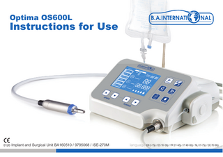
Optima OS600L
Instructions for Use
Implant and Surgical Unit BA160510 / 9795068 / ISE-270M
language EN 2-15p / ES 16~30p / FR 31~45p / IT 46~60p / NL 61~75p / DE 76~90p
EN Instructions for use
Implant and Surgical Unit BA160510 / 9795068
Symbols
Contents Catalog number
Chapter 1. Introduction
2
Chapter 2. Safety Information (Precautions and Warning)
2
Chapter 3. Description
3
Manufacturing Date
Chapter 4. Installation
6
BF type applied part
Chapter 5. Operation
8
Chapter 6. Maintenance
13
Chapter 7. Troubleshooting
14
Consult operating instructions
Chapter 8. Accessories and Service
15
Do not dispose with domestic waste
Chapter 9. Product Disposal Guideline
15
Annex A
91
Serial number Manufacturer Authorized representative in the European Community
Alternating current Keep dry Caution
IPX1
Water proof grade Distributor 1
Chapter 1. Overview 1.1 Operating Principle This device is an unit that consists of a main body, BLDC (brushless DC) motor, and foot pedal switch for driving and operating a handpiece for dental implant procedures, to be used in dentistry in the field of implant surgery. The main body of this device is powered by an external power supply that converts alternating current to direct current, which turns the BLDC motor; the rotation power of which combines with the handpiece to perform the dental implant procedure. The main body of the implant unit can be adjusted in terms of its torque, rotation speed, water injection volume, and rotational direction. The BLDC motor can be operated using the foot pedal switch. 1.2 Purpose of Use This is an engine used to power handpieces used for implants when performing dental implant procedures. 1.3 Users Only qualified dentists may use this device in a professional environment.. 1.4 Indications of Use 1) Where there is an absence of gum or teeth caused by cavities, gum disease, accidents or tumors. 2) Where enamel ablation is not recommended so as to protect the adjacent natural teeth. 3) Where the patient does not want denture treatment. 4) Where the patient wants to replace partial or full dentures that were previously used with a fixed-type dental prosthesis. 5) Where the patient wants full dentures to be replaced with some partial dentures and some fixed-type. 6) Where the patient requires implant support in relation to the lower dentures to maintain the full denture and also improve its function. 1.5 Checklist Prior to Use 1) Be sure to read the user manual prior to use. 2) Only to be used by a professional in a professional environment.. 3) Not to be used for anything other than its intended use.
Chapter 2. Safety (Warnings and Cautions) 2.1 Risks 1) If the cause of malfunction is unknown or if it cannot easily be resolved, please contact your dealer or your nearest BA repair centre. 2) If the display shows incorrect information, please contact your dealer or your nearest BA repair centre immediately. 3) Do not let the patients come into contact with the signal input piece, the signal output piece or other connecting pieces. 2.2 Notice 1) This product was designed to be used in implant procedures. The device should only be used in accordance with its intended usage and method. 2) The safety of the patient comes first and foremost. Be sure to pay sufficientattention when using the device. 3) Carefully study the user manual prior to use. Please familiarise yourself with the function of each part before using. 4) The main body and foot pedal switch of the implant unit cannot be cleaned in an autoclave. If the main body becomes contaminated, disconnect the power and clean with a clean, damp cloth, then wipe away the moisture with a dry cloth. 5) Prior to plugging in the device, check to confirm that the input voltage matches that of the device. 6) Any used water injection tube should be disposed of as medical waste. 2
2.3 Caution 1) Never attempt to disassemble or modify the device. Once the device is disassembled,you will no longer be entitled to after sales service from the manufacturer. 2) Never add oil to the inside of the BLDC motor. This can cause the bearings to malfunction and get hot. 3) Do not use thinner, benzene or any other solvents to clean. 4) Use only products and supplies that are prescribed by the specifications of the manufacturer. 5) If the power cord or plug socket is broken or damaged, do not use the deviceand inquire with the manufacturer. This could pose a risk of electric shock or fire. 6) When removing the power cord from the socket, be sure to pull the plug head, and do not do this with wet hands. Do not use the device with the power plug loosely connected. This could pose a risk of electric shock or fire. 7) Do not install near a heat source, and do not place near lit candles or cigarettes. This could pose a risk of fire. 8) Determine if there are any elderly, sick, injured, disabled persons, pregnant women or children near where the device is installed, and keep a close eye on such persons. Do not leave children alone with the device. 9) Ensure that the main body of the implant engine and the foot pedal do not come in contact with water, saline solution or other contaminants. If the device is not operating properly, or contaminants have entered the product, do not operate the device under any circumstances and inquire with the manufacturer instead. 10) Please use the device in accordance with the use stated in this user manual and refrain from using the device for any other purpose than that recommended by the manufacturer. The manufacturer will not be held liable for any accidents caused by a disregard for the instructions in the manual. 11) The external equipment for connecting the signal input piece, signal output piece or other connecting pieces must meet the IEC publication standards. 2.4 Warning 1) Prior to or during use, if you notice any abnormal symptoms including vibration, heat or abnormal noise, discontinue any use immediately and inspect the device. 2) Always use earthed socket for power supply. 3) With regard to tools used for implant procedure, please maintain the speed recommended by the manufacturer. Exceeding the recommended speed carried the risk of an accident.
Chapter 3. Product Description 3.1 Description of System, Components and Functions
※ Handpiece – sold separately
Motor (BA160530)
Main controller (BA160510)
3
Foot switch (BA160535)
3.1.1 Main Controller (BA160510) 1) Front
2) Rear Display
Power cable terminal
Rotation button Program button Memory button
Connection for irrgation hanger
Gear ratio button Coolant button Water injection pipe fixture
Groove on irrigation hanger
Motor connection
Speed Up/Down button
Torque Up/Down button
Optic LED button
Fuse box Power switch
3.1.3 Motor (BA160530)
3.1.2 Foot switch (BA160535) Hanger hole
Foot switch connector
Foot switch coable Coolant button
Foot switch terminal
Rotation button
Handpiece connection
Motor connection
Program button Optic LED
Operation button
4
3.2 Product Performance 1) Main controller (BA160510) Power Supply voltage
220V
Frequency
60HZ
Power Consumption
150VA
Max. Coolant flow rate
130 ml/min
Fuse
2 × 250 × T2.0AH
Dimension
300×230×135 ㎜ [Width×Length×Height]
2) Motor (BA160530) Max. Speed
40,000 rpm
Max. Torque
7 Ncm
Max. Current
6A
Dimension
Ø24 × L100 ㎜
Optic
White LED
Weight
165g
Coupling
ISO 3964
3) Foot Switch (BA160535) Speed control
Variable
Control Functions
Program control / Coolant control / Forward / Reverse
Control Functions
IPX1
3.4 Environmental Conditions (Storage, Relocation, Operation) 1) Storage conditions Temperature : -10°C ~ +50°C Humidity : 10 ~ 85% Air pressure : 500hPa ~ 1060hPa
2) Relocation conditions Temperature : -10°C ~ +50°C Humidity : 10 ~ 85% Air pressure : 500hPa ~ 1060hPa
3) Operation conditions Temperature : +10°C ~ +35°C Humidity : 30 ~ 85% Air pressure : 700~1060 hPa
5
Chapter 4. Installation 4.1 Installation of hanger and Foot switch hanger 4.1.1 Installation of hanger
4.1.2 Installation of Foot switch hanger
① Insert irrigation hanger into hanger hole.
① Insert foot switch hanger into hanger hole.
② Fix by connecting hanger bolt.
② Fix by connecting hanger bolt.
4.2 Connection of Motor
4.3 Connection of power cord and foot switch
① Plug the motor connector flush into the groove.
① Connect power cable to power cable terminal.
② Connect the motor connector CAP.
② Connect Foot switch connector to Foot switch terminal. Be careful to fit into the groove upon connection.
Be careful when plugging in the connector ①
6
②
4.4 Installation of irrigation tube External spray nozzle
Irrigation tube
Irrigation tube
③ Open Irrigation cover by pressing Push button. 20:1
Irrigation tube
Tube clip
① Attach the irrigation tube to the straight or contra-angle handpiece.
Push button
④ Put Irrigation tube in the groove.
Connect irrigation cover and Irrigation tube Internal spray nozzle
⑤ Close Irrigation cover.
‘Y’tube
⑥ Close the tube clamp. External spray nozzle ‘Y’tube
Irrigation tube Tube clamp
⑦ Open the tube clamp before start-up.
Coolant container Tube clip
nt
la oo
p
cli
le
ab
rc
to Mo
⑧ Stick the insert needle into the coolant container. ② Attach the motor cable and irrigation tube in regular intervals using the coolant clip.
n tio
⑨ Hook-in the coolant container on the bottle holder.
e
tub
Insert needle
iga
Irr
C
7
Chapter 5. Operation 5.1 General use 1) Turn on the Power switch of implant engine controller
① Connect the engine to the power cable. ② Turn the engine on at the power switch.
2) Programs are selected in turn by pressing Foot switch or P button of implant engine controller. 3) Check the displayed torque, rotation speed, irrigation flow rate, gear ratio and direction of rotation. 4) It starts rotating upon pressing Foot switch. It rotates at low speed with light press on Foot switch and rotates at full speed with hard press. When the irrigation flow rate is preset, the pump starts rotating as well. 5) When load reaches the maximum value of preset torque, motor stops rotating. 6) It stops rotating upon releasing Foot switch. 7) Turn off the implant engine controller
① When not in use, turn off the engine at the power switch ② Disconnect the engine from the power cable
8
5.2 Program Mode 5.2.1 Selecting a program
A user selects a program necessary for surgery with this button. Program cycles through numbers 1 to 6 when pressing the program button each time. It changes in order of Drilling→Tapping→Remove Tap→Implant→Remove→Rock screw. A white border highlights the selected program.
Program Button
5.2.2 Thread cutting function
Program Button
Activating the thread cutting function is only possible with the tapping program.
① Foward rotation
5.2.3 Deleting a program
② Reverse rotation
when loading beyond the preset torque limit value
when foot sweetch is released
④ Foward rotation
when foot sweetch is on
5.2.4 Restoring programs
This function deletes unnecessary and unused programs. Select an unused program and delete it by pressing this button for more than 2 seconds. Program Button
③ Rotation stop
This function restores the deleted programs. Restores all deleted programs pressing this button more than 2 seconds.
Rotation Button
9
5.3 Memory function 5.3.1 Memory button Press the memory button to access memory address where detailed figures (Gear ratio, Torque, Speed, For/Rev, Coolant) of each function in program are saved. Memory address cycles through numbers 1 to 9 upon pressing Memory button each time. ...
Memory 1
Memory Button
① Drilling set value
① Drilling set value
...
② Tapping set value
...
③ Remove tap set value
The memory number(1-9) currently selected is being displayed.
Memory 9
...
...
④ Implant set value
② Tapping set value ③ Remove tap set value ④ Implant set value
...
⑤ Remove set value
...
⑥ Rock screw set value
⑤ Remove set value ⑥ Rock screw set value
※ Initial setting (Factory settings) : Memory Program
Gear ratio
Torque [Ncm]
Speed [rpm]
Motor direction
Coolant level
Drilling
20:1
55
1,500
Forward
4
Tapping
20:1
40
50
Forward
3
Remove tap
20:1
40
50
Reverse
3
Implant
20:1
40
50
Forward
3
Remove
20:1
55
50
Reverse
0
Rock screw
20:1
10
50
Forward
0
5.3.2 Saving data Save detailed figures in memory which are currently set (Gear ratio, Torque, Speed, For/Rev, Coolant) for each function in program. press and hold the memory button for 2sec to start saving data. A beep will sound and ‘No.’ will continuously flash. Press the Memory button again to select the memory address where data is to be saved. Press the memory button for 2sec once more to save the data. ‘No.’ will stop flashing and 2 beeps will sound again when saving is completed Memory Button
The memory number (1~9) currently selected is being displayed. ‘No.’ flashes continuously until data is saved. 10
5.4 Setting direction of motor rotation The initial setting is Forward direction and Reverse is selected upon pressing the button The letters "REV" and arrow are turned on upon selecting Reverse, and a beep will sound.
Rotation Button
FOR.
① The letters "FOR" and arrow are turned on upon selecting Forward.
REV.
② The letters and arrow falsh during the motor operation. ③ The same goes for selecting Reverse. A beep sound occurs when switching between Forward and Reverse.
5.5 Gear ratio change It selects gear ratio in accordance with that on a handpiece. Gear ratio alters upon pressing Gear ratio button each time. Gear Ratio : ① 1:1 Gear ratio Button
② 1:2
③ 16:1
④ 20:1
⑤ 27:1
⑥ 32:1
It alters in turn from number ① to ⑥ upon pressing the button each time.
5.6 Optic LED On/Off Press Optic/Non optic button to operate LED within the motor BA160530 which is designed for Optic.
Optic LED Button
① When the LED is on, the LED symbol is displayed. ② During the motor operation, LED is on. ③ When motor stops, the LED turns off after 3 seconds ④ When the LED is off, the symbol not displayed.
5.7 Controlling Irrigation flow rate Water injection rate alters in turn by five levels upon pressing Coolant button. 30 ml/min Coolant Button
60 ml/min 90 ml/min 110 ml/min 130 ml/min
11
5.8 Change in torque value Torque section on the display flashes upon pressing torque button. Torque is controlled using the button for adjusting set value. Torque setting mode is exited by pressing Torque button again or another button for another function or when the motor is operated. Torque Up/Down Button
Change the torque value of motor, 5 N.cm increase.
5.9 Change in speed
Gear ratio
Torque(Ncm)
Gear ratio
Torque(Ncm)
1:1
-
1:2
-
16:1
5~60
20:1
5~70
27:1
5~80
32:1
5~80
Speed section on the display flashes upon pressing Speed button. Speed is controlled using the button for adjusting set value. Speed setting mode is exited by pressing Speed button again or another button for another function or when the motor is operated. SPEED Up/Down Button
Gear ratio
Speed(rpm)
Gear ratio
Speed(rpm)
1:1
200~40,000
1:2
400~80,000
16:1
12~2,500
20:1
10~2,000
27:1
7~1481
32:1
6~1250 5.10 Operation of implant engine Implant engine operates upon completion of all settings. When motor operates by pressing foot switch, the letter 'R' on display and the surrounding border flickers in turn. The torque and speed indicate the current figures and a beep sounds when altered torque value reach 90% of set value. Motor stops when it reach 100% of set value.
5.11 Auto Calibration When users press the speed up and down button simultaneously for 2 seconds, auto calibration is executed. When auto calibration is executed, the motor starts with a beep sound. Auto calibration is completed when speed increases from 0 to 40,000 RPM on the display and the motor will stop when it's done. Auto calibration is recommended when actual speed of the motor is different from speed on the display. SPEED Up/Down Button
Auto Calibration is performed upon simultaneously pressing both buttons longer than 2 seconds. Auto calibration is recommended after sterilization. 12
Chapter 6. Maintenance 6.1 Manual cleaning 1) Separate the motor and Foot Switch connected in the Control Unit. 2) Prepare a cloth (preferably cotton) or soft brush moistened with isopropyl alcohol. 3) Clean foreign substance on the entire surface and in the gaps with cloth or brush soaked in isopropyl alcohol for at least 3 minutes. 4) Repeat the cleaning process if foreign substance is found. Clean the product before and after use. 6.2 Inspection 1) Inspect whether there is any foreign substance visible to the naked eye. 2) Check the operating condition. 3) Repeat the cleaning process if foreign substance is found. 4) Repeat the above procedure for every single use. 6.3 Sterilization Sterilization Applicable Products : Motor, Motor connection cable 1) Disconnect the motor cable from controller. 2) Attach the motor cap to the handpiece connection of the motor. 3) Sterilize the motor equipped with the cap and motor cable either before or after use under the following conditions. Type
Sterilization conditions
Drying time
Gravity displacement type sterilizer
At least 30 minutes at 121℃
30 minutes.
Air-removal steam sterilization(pre-vacuum)
At least 4 minutes at 132℃
30 minutes.
• Please sterilize after using the product. • We do not recommend you to sterilize on plasma sterilization or EOG sterilization. • Do not disconnect the motor from the motor cable when sterilizing.
※ Sterilization by moist heat(134~135℃) for 3 minutes in a steam sterilizer (Autoclave) 6.4 Change fuse ① Switch off and unplug the unit as per 5.1
② Carefully remove the fuse box
③ Replace the fuses with new ones of the same fuse type.
Extra fuse Needed to change 13
④ Re-insert the fuse box
Chapter 7. Troubleshooting 7.1 Description of Error Message 7.1.1 Error display screen Upon occurrence of error, a warning sound is made and then the number subject to the error flickers on error display part of the screen. Error code
Error number(E1~E8) will pop up and keep flashing depending on each cause.
Status
Cause of error Defective motor hall sensor, poor connection Defective motor and poor connection
Remedy
E1
Error on motor sensor
Contact your BA repair centre
E2
Motor error
E3
Overload error
Overload on motor
E4
Error on cooler temperature (Heat sink temperature error)
Cooler being overheated, breakdown of temperature sensor
Restart after turning off the power then leave unit on standby Restart after turning off the power then leave unit on standby
E5
Transformer error
Defective transformer, overheating
Contact your BA repair centre
E6
Error on circuit and voltage
Defective circuit
Contact your BA repair centre
E7
Error on pedal connection
Poor pedal connection
Reconnecting and checking the pedal
Reconnecting and checking the motor
7.2 Breakdown Description Error
Display screen does not appear upon turning on the power on.
Motor does not operate upon stepping on the foot switch.
Cause of error
Remedy
Inaccurate connection of power cord
Checking plug connection
Breakdown of power cord
Contact your BA repair centre
Breakdown of fuse
Replacing fuse
Inaccurate connection of power cord
Checking plug connection
Breakdown of foot switch
Contact your BA repair centre
14
Chapter 8. Accessories 8.1 Accessories
Motor (BA160530)
Irrigation hanger (BA160543)
Foot switch (BA160535)
Motor connection cable (BA160540)
Foot switch hanger (BA160544)
Irrigation tube (BA690110)
Foot switch cable (BA160541)
Tube holder (BA160545)
8.2 Information on After-Sale Service ▶ Distributor: B.A. International Ltd. ▶ Address: Unit 9, Kingsthorpe Business Centre, Studland Road, Northampton, NN2 6NE, UK. ▶ Made in : Republic of Korea
Hanger bolt (BA160546)
Power cable (BA160542)
Motor cap for autoclave (BA160547)
▶ Contact: +44 (0)1604 777700
8.3 Warranty ▶ Implant engine controller, motor : 1 year ▶ Damage due to customer's mistake, misuse of the product and normal abrasion of motor bearing are not included.
Chapter 9. Disposal 10.1 Disposal guideline 10.1.1 Disposal of Main controller and foot switch and motor ▶ Follow your country specific laws, directives, standards and guidelines for the disposal of used electrical devices. ▶ Ensure that the parts are not contaminated on disposal. 10.1.2 Disposal of the packaging material ▶ All packaging materials have been selected according to environmentally compatible and disposal aspects and can be recycled. Please send old packaging materials to the relevant collection and reprocessing system. This way, you will contribute to the recycling of raw materials and the avoidance of waste. 15
Instruction for use
Stand (BA160548)
www.bainternational.com
Annex A 10.1 Electromagnetic Compatibility The product is suitable for use in an specific electromagnetic environment. The customer and/or the user of the product should assure that it is used in an electromagnetic environment as described below. Emission Test
Compliance
RF-emission CISPR 11
Group 1
RF-emission CISPR 11
Class A
Harmonic emissions IEC 6100-3-2 Voltage fluctuations/ flicker emissions IEC 61000-3-3
Complies
Class A
Electromagnetic Environment Guidance The product use RF energy only for its internal function. Therefore, its RF emissions are very low and not likely to cause any interference in nearby electronic equipment. The product is suitable for use in all establishments, including domestic establishments and those directly connected to the public low-voltage power supply network that supplies buildings used for domestic purpose.
10.2 Electromagnetic Immunity The product is suitable for use in a specific electromagnetic environment. The customer and/or the user of the product should assure that it is used in an electromagnetic environment as described below. Emission Test
IEC 60601- Level
Compliance Level
Electrostatic discharge(ESD) IEC61000-4-2 Electrical fast transient/bursts IEC61000-4-4 Surge IEC61000-4-5
± 6kV contact ± 8kV air ± 6kV contact ± 8kV air ± 6kV contact ± 8kV air
± 6kV contact ± 8kV air ± 6kV contact ± 8kV air ± 6kV contact ± 8kV air
Voltage dips, short interruptions and voltage variations on power supply input lines IEC61000-4-11
<5% UT (>95% dip in UT) for 0.5 cycle 40% UT (60% dip in UT) for 5 cycles 70% UT (30% DIP IN UT) for 25 cycles <5% UT (>95% dip in UT) for 5 sec
<5% UT (>95% dip in UT) for 0.5 cycle 40% UT (60% dip in UT) for 5 cycles 70% UT (30% DIP IN UT) for 25 cycles <5% UT (>95% dip in UT) for 5 sec
Mains power quality should be that of a typical commercial and/or hospital environment. If the user of the product requires continued operation during power mains interruptions, it is recommended that the product be powered from an uninterruptible power supply or a batter
3A/m
3A/m
Power frequency magnetic fields should be at levels characteristic of a typical location in a typical commercial or hospital environment.
Power frequency (50/60 Hz) magnetic field IEC 61000-4-8
Electromagnetic Environment Guidance Floor should be wood, concrete or ceramic tile. If floors are covered with synthetic material, the relative humidity should be at least 30 % Mains power quality should be that of a typical commercial and/or hospital environment Mains power quality should be that of a typical commercial and/or hospital environment
91
Emission Test
IEC 60601- Level
Compliance Level
Conducted RF IEC 61000-4-6
3 Vrms 150 kHz to 80 MHz
3 Vrms
Radiated RF IEC 61000-4-3
3V/m 80 MHz to 2.5 GHz
3 Vrms
Electromagnetic Environment Guidance Portable and mobile RF communications equipment should be used no closer to any part of the product, including cables, than the recommended separation distance calculated from the equiation applicable to the frequency of the transmitter. Recommended separation distance : d = 1.2√P d = 1.2√P for 80MHz to 800MHZ d = 2.3√P for 800 MHz to 2.5 GHz where P is the maximum output power rating of the transmitter in Watt (W) according to the transmitter manufacturer and d is the re-commended separation distance in meters (m) Field strengths from fixed RF transmitters, as determined by an electromagnetic site survey(a), should be less than the compliance level(b) in each frequency range Interference may occur in the vicinity of equipment marked with the symbol described lateral.
Note 1: At 80 MHz and 800 MHz, the higher frequency range applies. Note 2: These guidelines may not apply in all situations. Electromagnetic propagation is affected by absorption and reflection from structures, objects, people and animals. (a) Field strengths from fixed transmitters, such as base stations for radio (cellular/cordless) telephones and land mobile radios, amateur radio, AM and FM radio broadcast and TV broadcast cannot be predicted theoretically with accuracy. To assess the electromagnetic environment due to fixed RF transmitters, an electromagnetic site survey should be considered, if the measured field strength in the location in which the product is used exceeds the applicable RF compliance level above, the product should be observed, additional measures may be necessary, such as reorienting or relocating the product. (b) Over the frequency range 150 kHz to 80 MHz, field strengths should be less than 3 V/m. 10.3 Recommended Separation Distances between portable and mobile HFcommunications equipment and the product The product is intended for use in an electromagnetic environment in which radiated RF disturbances are controlled. The customer or the user of the product can help prevent electromagnetic interference by maintaining a minimum distance between portable and mobile RF communications equipment (transmitters) and the product – according on output power and frequency of the communications equipment – as recommended in the following table. Separation distance according to the frequency of transmitter in meter (m) Rated maximum output power of transmitter in watts (W) 150 kHz to 80 MHz d = 1.2√P 80 MHz to 800 MHz d = 1.2√P 800 MHz to 2.5 GHz d = 2.3√P 0.01 0.23 0.12 0.12 0.01 0.73 0.38 0.38 0.1 2.3 1.2 1.2 10 7.3 3.8 3.8 100 23 12 12 For transmitters rated at a maximum output power not listed above, the recommended separation distance d in meters (m) can be estimated using the equation applicable to the frequency of the transmitter, where P is the maximum output power rating of the transmitter in watts (W) according to the transmitter manufacturer. Note 1: At 80 MHz and 800MHz, the higher frequency range applies. Note 2: These guidelines may not apply in all situations. Electromagnetic propagation is affected by absorption and reflection from structures, objects, people and animals. 92
The EU directive 93/42/EEC was applied in the design and production of this medical device Distributor: B.A. International Ltd. Address: Unit 9, Kingsthorpe Business Centre, Studland Road, Northampton, NN2 6NE, UK. Contact: +44 (0)1604 777700
www.bainternational.com
MicroNX co., branch office Address: Karl-Marx-Str. 6 16540 Hohen Neuendorf Germany Contact: +49 (0)3303 5412323
Fax: +49 (0)3303 5412324
Manufacturer: MicroNX co., Ltd. Address: 22, Maeyeo-ro 1-gil, Dong-gu, Daegu, 41059 Republic of Korea Contact: +82 53 650 1000
www.micronx.co.kr
Made in : Republic of Korea
04. 2019